Circuit switching on and switching off device, control method and computer storage medium

A control method and on-off technology, which is applied in the direction of circuit devices, emergency protection circuit devices, parts of emergency protection devices, etc., to achieve the effects of saving space, realizing delayed tripping, and improving utilization efficiency

Pending Publication Date: 2018-10-12
GD MIDEA AIR-CONDITIONING EQUIP CO LTD +1
View PDF9 Cites 1 Cited by
  • Summary
  • Abstract
  • Description
  • Claims
  • Application Information

AI Technical Summary

Problems solved by technology

[0005] The main purpose of the present invention is to provide a circuit on-off device, aiming to solve the technical problem that the existing anti-power-off device and air switch are set separately, and rely on the rated value of the air switch to control the operation of electrical appliances

Method used


Image

  • Circuit switching on and switching off device, control method and computer storage medium
  • Circuit switching on and switching off device, control method and computer storage medium
  • Circuit switching on and switching off device, control method and computer storage medium

Examples


Embodiment 1

[0034] The present invention proposes a circuit breaking device 100 .

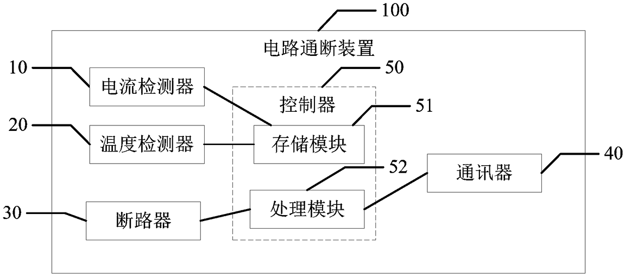
[0035] refer to figure 1 , in the embodiment of the present invention, the circuit breaking device 100 includes a housing (not shown), and the circuit breaking device 100 also includes a current detector 10, a temperature detector 20, The circuit breaker 30, the communicator 40 and the controller 50; the controller 50 is electrically or signally connected to the current detector 10; the controller 50 is electrically or signally connected to the temperature detector 20; the The controller 50 is electrically or signally connected to the circuit breaker 30; the controller 50 is electrically or signally connected to the communicator 40; the temperature detector 20 is arranged adjacent to the circuit breaker 30 to detect the circuit breaker 30 and send to the controller 50, the current detector 10 detects the total current value in the circulation circuit and sends to the controller 50.

[0036] Further, the ...

Embodiment 3

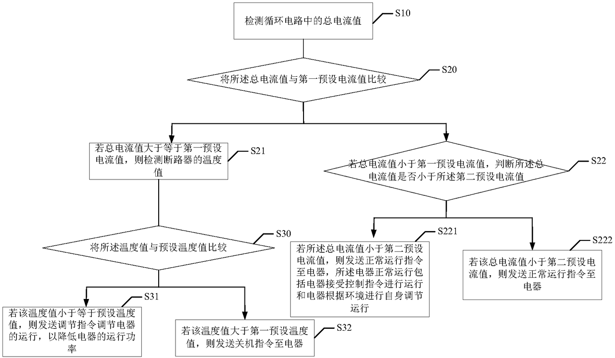
[0052] Embodiment 3: combined reference image 3 with Figure 4 , the present application also proposes a control method for the circuit on-off device 100, including:

[0053] Step S10: detecting the total current value in the circulating circuit;

[0054] The circulation circuit refers to the total circuit connected to the circuit switching device 100. Taking the household circulation circuit as an example, the total current value refers to the total current value generated by all electrical appliances in the home during operation.

[0055] Step S20: comparing the total current value with a first preset current value;

[0056] By comparing the total current value with the first preset current value, the interval of the total current value can be judged. The first preset current value is the rated current value of the household, and the rated current value can be set according to the characteristics of the household air switch. Current value, respectively set the functional...


PUM


Abstract

The invention discloses a circuit switching on and switching off device, a control method and a computer storage medium, wherein the circuit switching on and switching off device comprises a shell, and further comprises a current detector, a temperature detector, a breaker, a communicator and a controller all arranged in the shell; the controller is in electrical connection or signal connection with the current detector, the temperature detector, the breaker and the communicator; the temperature detector is arranged to be close to the breaker so as to detect a temperature value of the breakerand send the temperature value to the controller, and the current detector detects a total current value in a circulating circuit and sends the total current value to the controller. The device, the method and the computer storage medium provided by the invention aim at solving a technical problem that the existing power outage preventing device is arranged to be independent from an air switch andcontrol of operation of electrical appliances is dependent on a rated value of the air switch.

Description

technical field [0001] The invention relates to the technical field of circuit control, in particular to a circuit on-off device, a control method of the circuit on-off device and a computer storage medium. Background technique [0002] At present, in households with households, the anti-power outage function generally depends on the control of the air switch, and the anti-power outage device installed is generally only for simple detection, and the anti-power outage device and air switch are two separate products. The current value is detected by the anti-power-off device, and then the circuit is turned on and off by the air switch. The electrical appliances in the home mainly rely on the rated current value of the air switch as the judgment value when realizing the anti-power outage function. When the rated current value is higher than the rated current value, the frequency is reduced or shut down, and when the rated current value is lower than the rated current value, the...

Claims


Application Information

Patent Timeline
Patent Type & Authority Applications(China)
IPC IPC(8): H02H3/08H02H1/00
CPCH02H1/0007H02H1/0092H02H3/08
Inventor 袁光
Owner GD MIDEA AIR-CONDITIONING EQUIP CO LTD
Why Eureka
Try Eureka