Steel bar bending machine

A steel bar bending and steel bar technology, which is applied in the field of electric tunnel construction machinery, can solve the problems that the bending radius of electric tunnel steel bars cannot be met, the bending radius of steel bars is large, and the bending moment is increased, so as to improve the processing convenience and efficiency. The effect of prolonging the service life and improving the machining accuracy

Pending Publication Date: 2018-10-16
北京城乡隧盾国际建设工程有限公司
View PDF10 Cites 3 Cited by
  • Summary
  • Abstract
  • Description
  • Claims
  • Application Information

AI Technical Summary

Problems solved by technology

[0004] However, the bending radius of steel bars commonly used in power tunnel construction is relatively large, and the bending radius of the steel bars processed by the above-mentioned steel bar bending machine is limited by the diameter of the outer wall of the center pin shaft 21, and the bending radius is small, which cannot meet the requirements of

Method used


Image

  • Steel bar bending machine
  • Steel bar bending machine
  • Steel bar bending machine

Examples


Embodiment Construction

[0039] The present invention will be described in further detail below in conjunction with accompanying drawing, and the words " front ", " back ", " left ", " right ", " upper " and " lower " used in the following description refer to the direction in the accompanying drawing, word "Bottom" and "top", "inner" and "outer" refer to directions toward and away from, respectively, the geometric center of a particular component.

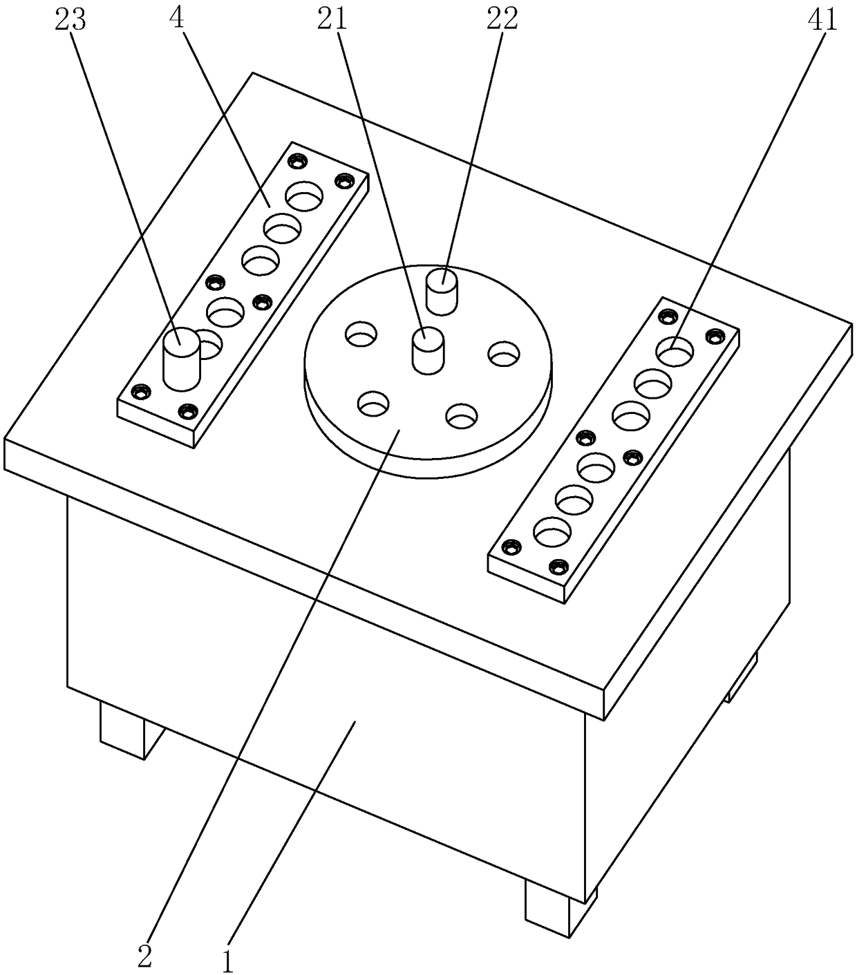
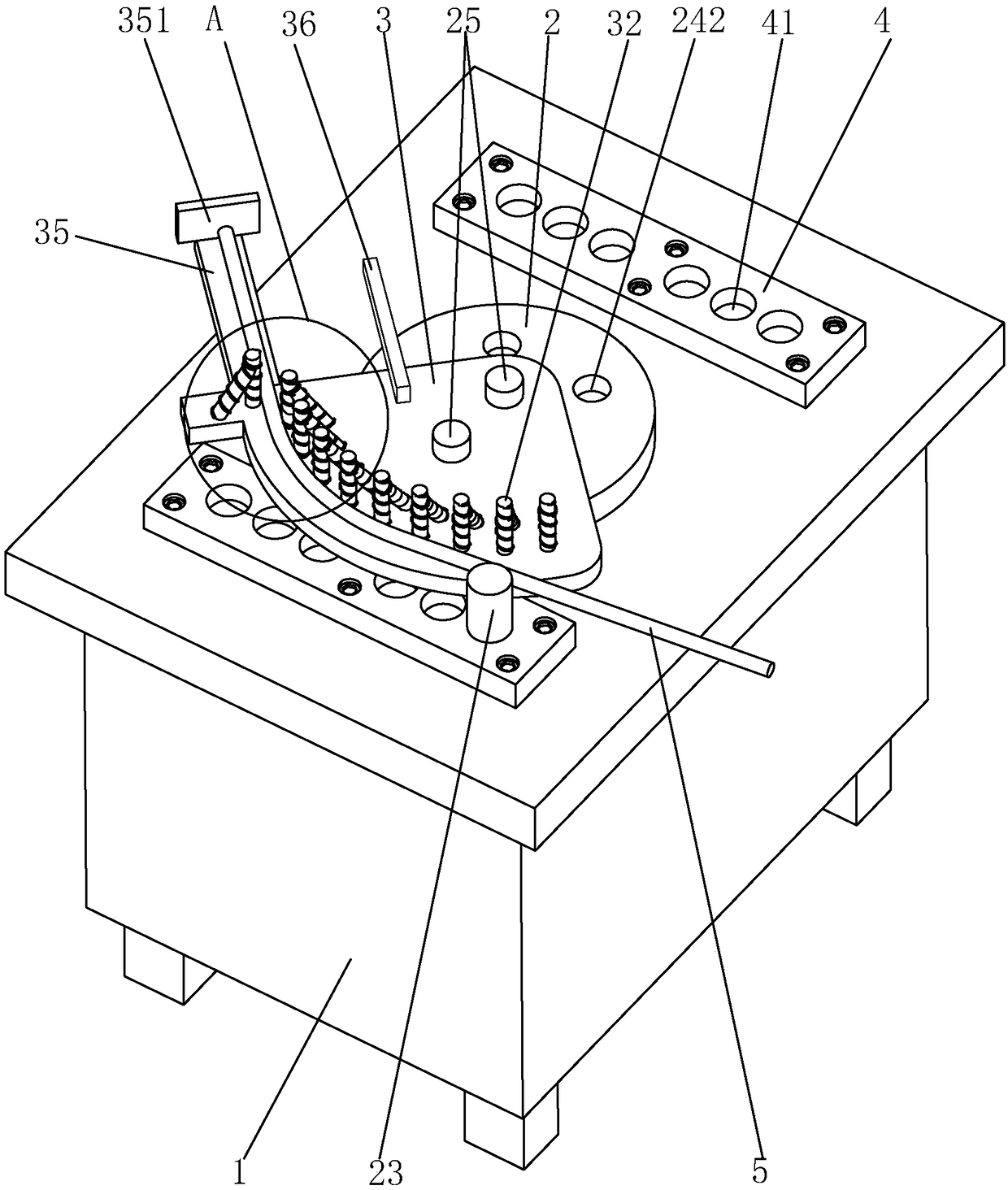
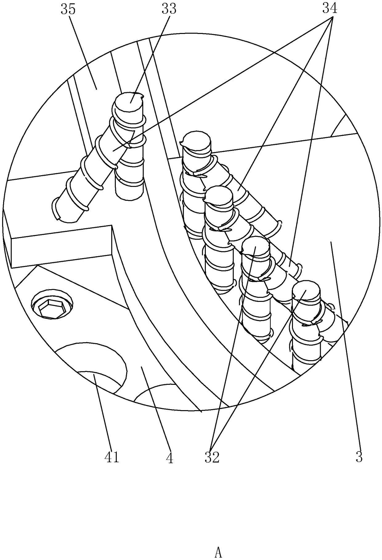
[0040] A steel bar bending machine such as figure 2 and image 3 As shown, including the machine tool 1, the top surface of the machine tool 1 is provided with a work plate 2, the top surface of the machine tool 1 on the side of the work plate 2 is provided with a support pin 23, the top surface of the work plate 2 is provided with a bending plate 3, and the top surface of the bending plate 3 A plurality of forming columns 32 arranged in an arc shape are provided on the surface, and a bending column 33 is provided on the top surface of the bending plate...


PUM


Abstract

The invention discloses a steel bar bending machine, and belongs to the technical field of electric power tunnel construction machinery. The technical scheme of the steel bar bending machine comprisesa machine tool, wherein the top surface of the machine tool is provided with a working disc; the working disc is connected to a driving part for driving the working disc to horizontally rotate, a supporting pin shaft is arranged on the top surface of the machine tool on one side of the working disc, and a bending disc is arranged on the top surface of the working disc; a plurality of forming columns are arranged on one side, close to the supporting pin shaft, of the top surface of the bending disc; the plurality of forming columns are arranged in an arc shape, and an arc-shaped center pointsto one side which is away from the supporting pin shaft; bending columns are further arranged on the top surface of the bending disc, and the bending columns are located on one side, close to the supporting pin shaft, of the forming columns. According to the steel bar bending machine, the plurality of forming columns which are arranged in the arc shape, the bending columns and the supporting pin shaft form three acting force points of the bent steel bar, the large bending radius can be conveniently machined, and the machine is not limited by shorter length or larger diameter of the steel bar,and therefore the time and labor are saved.

Description

technical field [0001] The invention relates to the technical field of electric tunnel construction machinery, in particular to a steel bar bending machine. Background technique [0002] In the construction of power tunnels, steel bars with different lengths and different bending radii are often used, and the steel bars are usually bent by a steel bar bending machine. figure 1 Shown is a conventional steel bar bending machine, including a cuboid-shaped machine tool 1, a working disk 2 is arranged on the top of the machine tool 1, and a motor is installed inside the machine tool 1, and the motor is connected to the central axis of the working disk 2 and drives the working disk 2 on the horizontal plane Turn inside. The center of the top surface of the work disk 2 is provided with a center pin 21, and the eccentric part of the top surface is provided with a bending pin 22. The top surface of the machine tool 1 on one side of the work disk 2 is fixed with a support pin 23, the...

Claims


Application Information

Patent Timeline
IPC IPC(8): B21F1/00
CPCB21F1/00
Inventor 张快生张林张伟张祥张玉棚白喂玲
Owner 北京城乡隧盾国际建设工程有限公司
Why Eureka
Try Eureka