Automatic electronic substrate machining equipment

A technology for processing equipment and electronic substrates, applied in the field of electronics, can solve the problems of lack of height and drilling angle adjustment, low degree of automation, and difficult operation, so as to improve drilling efficiency, high degree of automation, and reduce labor intensity. Effect

Inactive Publication Date: 2018-10-16
江苏卓燃高新科技有限公司
View PDF0 Cites 4 Cited by
  • Summary
  • Abstract
  • Description
  • Claims
  • Application Information

AI Technical Summary

Problems solved by technology

However, in some large-scale electronic substrate processing and production, it is often necessary to perform drilling operations, and the traditional electronic substrate drilling device has a low degree of automation and requires too much manual operation. Its operation is difficult and inefficient, and it does not have a high degree of As well as the adjustment of the drilling angle, its limitations are relatively large, and there are relatively large disadvantages, which need to be improved

Method used


Image

  • Automatic electronic substrate machining equipment
  • Automatic electronic substrate machining equipment

Examples


Embodiment Construction

[0017] All features disclosed in this specification, or steps in all methods or processes disclosed, may be combined in any manner, except for mutually exclusive features and / or steps.

[0018] Any feature disclosed in this specification (including any appended claims, abstract and drawings), unless expressly stated otherwise, may be replaced by alternative features which are equivalent or serve a similar purpose. That is, unless expressly stated otherwise, each feature is one example only of a series of equivalent or similar features.

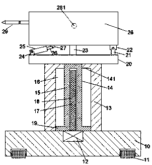
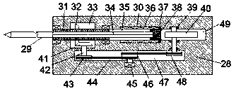
[0019] Such as Figure 1-2 As shown, a kind of automatic electronic substrate processing equipment of the device of the present invention includes a base 10, a support column 13 fixedly arranged on the top of the base 10, and a frame 28 arranged above the top of the support column 13, and the support column The top of 13 is provided with a support plate 20, and the center position of the top of the support plate 20 is fixed with a support pla...


PUM


Abstract

The invention discloses automatic electronic substrate machining equipment. The automatic electronic substrate machining equipment comprises a base, a supporting column fixedly arranged on the top ofthe base, and a rack arranged above the top of the supporting column. A supporting plate is erected on the top of the supporting column. A supporting table is fixedly arranged at the center position of the top of the supporting plate. The top of the supporting table abuts against the top end face of the rack. The top end faces of the parts, on the left side and the right side of the supporting table, of the supporting plate are provided with a first connecting arm and a second connecting arm correspondingly. A first connecting block and a second connecting block are fixedly arranged on the twosides of the bottom end face of the rack correspondingly. A hydraulic cylinder is hinged and installed to the first connecting arm, and a hydraulic rod of the hydraulic cylinder is hinged to the first connecting block. The second connecting arm and the second connecting block are installed in a hinged manner, a sliding cavity with a leftward opening is formed in the rack in a left-right extendingmanner, and a sliding block is arranged in the sliding cavity in a sliding manner.

Description

technical field [0001] The invention relates to the field of electronic technology, in particular to an automatic electronic substrate processing equipment. Background technique [0002] The electronic substrate is an important basis for the development of the electronics industry, the basic unit of electronic equipment, and is located at the front end of the electronics industry. However, in some large-scale electronic substrate processing and production, it is often necessary to perform drilling operations, and the traditional electronic substrate drilling device has a low degree of automation and requires too much manual operation. Its operation is difficult and inefficient, and it does not have a high degree of And drilling angle adjustment, its limitation is bigger, there is bigger drawback, needs improvement. Contents of the invention [0003] Aiming at the deficiencies of the above technologies, the present invention proposes an automatic electronic substrate pro...

Claims


Application Information

Patent Timeline
Patent Type & Authority Applications(China)
IPC IPC(8): B26F1/16B26D5/08B26D7/26B26D5/02B26D7/00
CPCB26F1/16B26D5/02B26D5/08B26D7/00B26D7/2628
Inventor 刘田田
Owner 江苏卓燃高新科技有限公司
Why Eureka
Try Eureka