Soil scraping assembly used for building industry
A technology for the construction industry and components, used in construction, earthmoving machines/shovels, etc., can solve the problems of low efficiency of manual excavation, and achieve the effect of high excavation efficiency and reasonable tool structure design.
- Summary
- Abstract
- Description
- Claims
- Application Information
AI Technical Summary
Problems solved by technology
Method used
Image

Examples
Embodiment Construction
[0026] In order to make the technical means, creative features, goals and effects achieved by the present invention easy to understand, the present invention will be further elaborated below in conjunction with illustrations and specific embodiments.
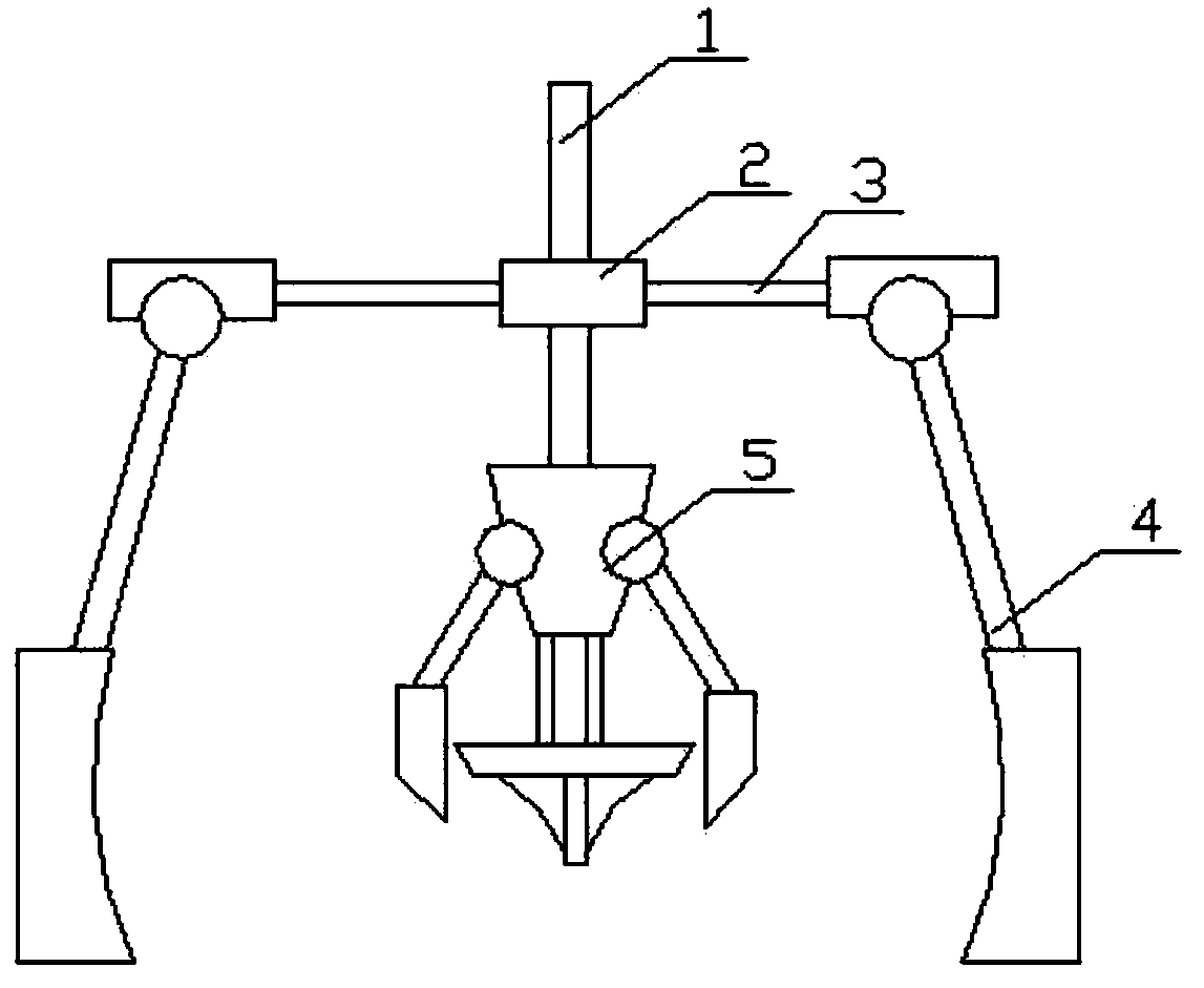
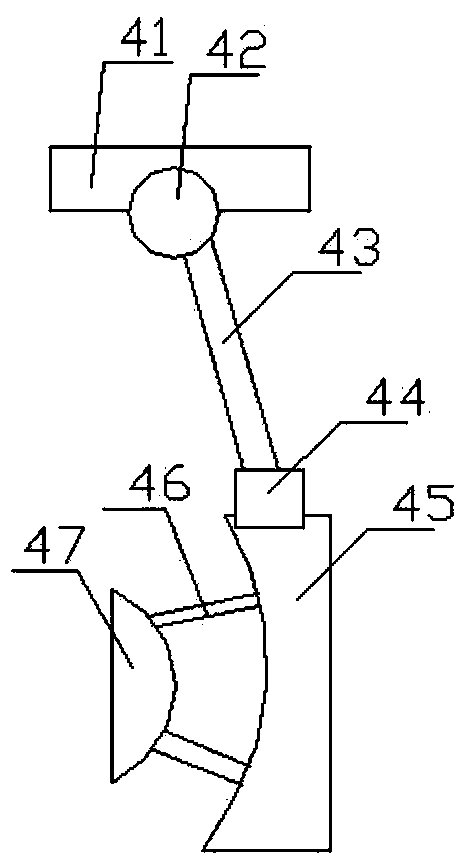
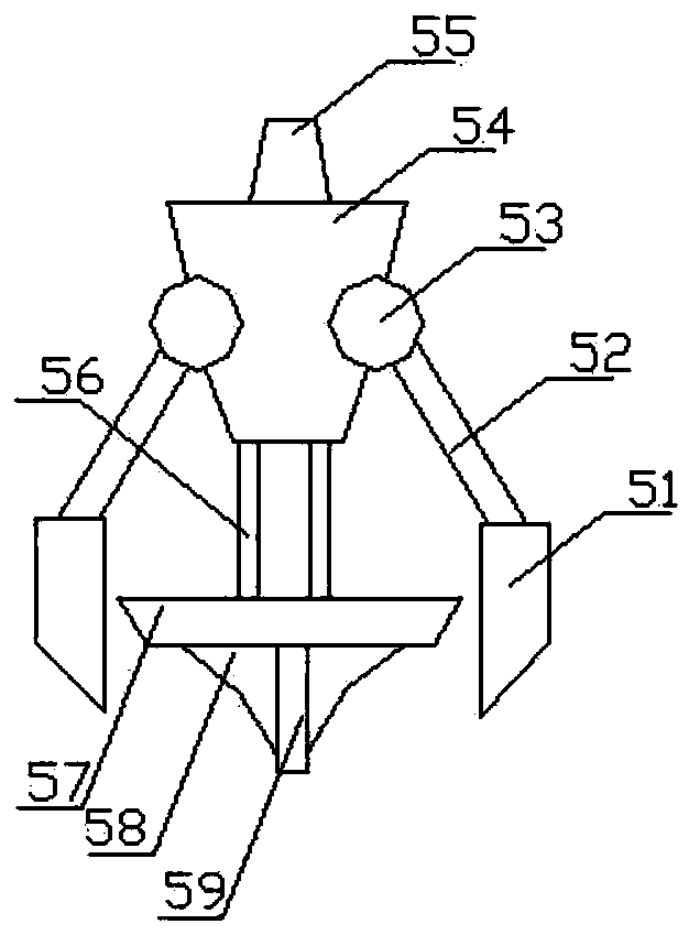
[0027] to combine Figure 1 to Figure 4 An earth excavating device for construction industry according to the present invention will be described in detail.
[0028] A digging device for the construction industry of the present invention comprises a center rod 1, and also includes a main mounting plate 2 screwed to the middle of the center rod 1 through threads, and a main mounting plate 2 screwed to the lower end of the center rod 1 through threads. The inner excavation part 5, the beam 3 radially penetrated in the main mounting plate 2 along the cross section of the main mounting plate 2, and the soil scraping component 4 screwed to the end of the beam 3 through threads; The two scraping parts 4 are axisymmetric with respect ...
PUM
 Abstract
Description
Claims
Application Information
PatSnap Eureka turns technology decisions into work you can execute. Powered by our Innovation Knowledge Graph, it runs expert workflows across engineering, life sciences, materials and intellectual property. Get your review-ready output in minutes.


