
Electromagnetic touch structure, side-in backlight display module and display

An edge-type backlight and electromagnetic touch technology, applied in the field of display devices, can solve the problems of the whole machine being unable to be used normally, disconnected, and unable to draw lines, etc., and achieve the effect of improving the writing abnormality of the whole machine and improving the signal response.

Active Publication Date: 2018-10-16
GUANGZHOU SHIYUAN ELECTRONICS CO LTD +1
View PDF6 Cites 4 Cited by
  • Summary
  • Abstract
  • Description
  • Claims
  • Application Information

AI Technical Summary

Problems solved by technology

[0002] In traditional technology, electromagnetic touch technology is applied to large-size touch all-in-one machines (above 40 inches), especially when the display module adopts a side-type backlight module design, due to the metal backlight of the display module The board is close to the electromagnetic antenna module, so that when electromagnetic writing is performed, the electromagnetic signal will be partially shielded by the metal backplane, resulting in a decrease in the magnetic flux of the electromagnetic coil of the electromagnetic antenna module, which will make it difficult to recognize the writing signal, which will make the whole machine When writing or controlling with an electromagnetic writing pen, there will be problems such as disconnection and failure to draw lines, which will cause the whole machine to fail to work normally.

Method used


Image

  • Electromagnetic touch structure, side-in backlight display module and display
  • Electromagnetic touch structure, side-in backlight display module and display
  • Electromagnetic touch structure, side-in backlight display module and display

Examples


Embodiment Construction

[0029] Embodiments of the present invention are described in detail below, examples of which are illustrated in the accompanying drawings, wherein like numerals designate like parts throughout the drawings. The embodiments described below by referring to the figures are exemplary only for explaining the present invention and are not construed as limiting the present invention.

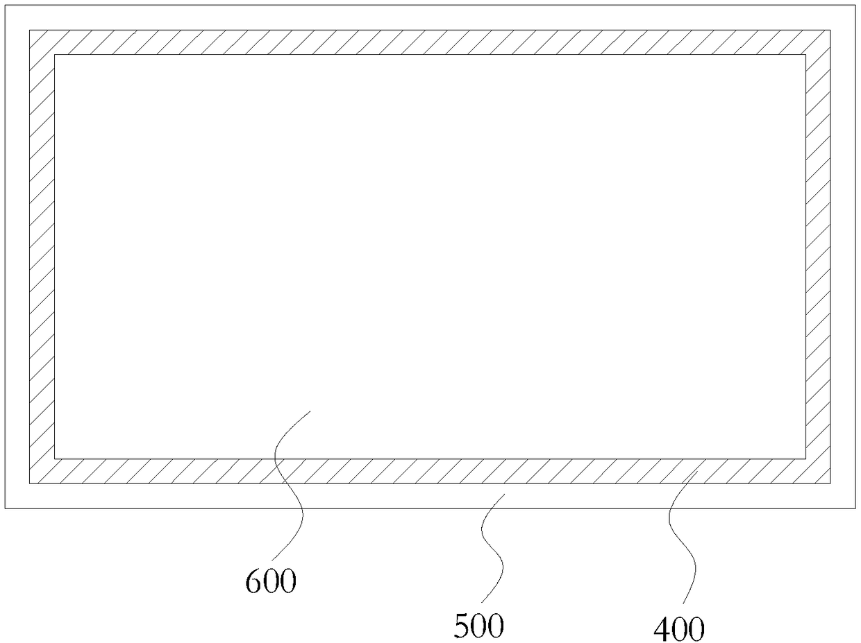
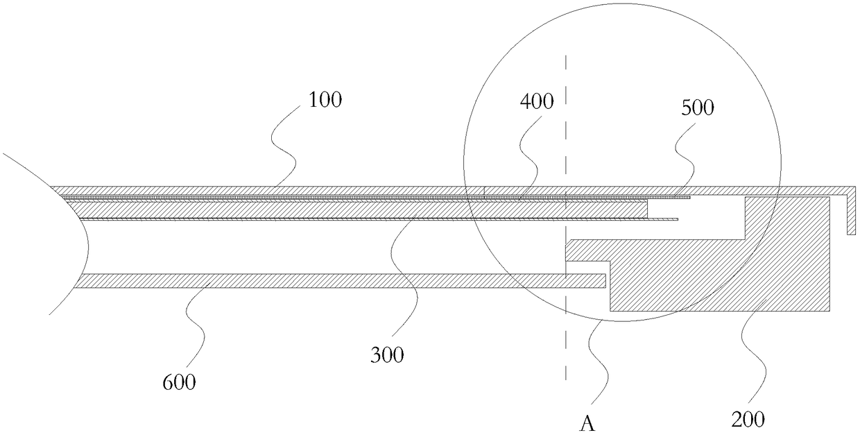
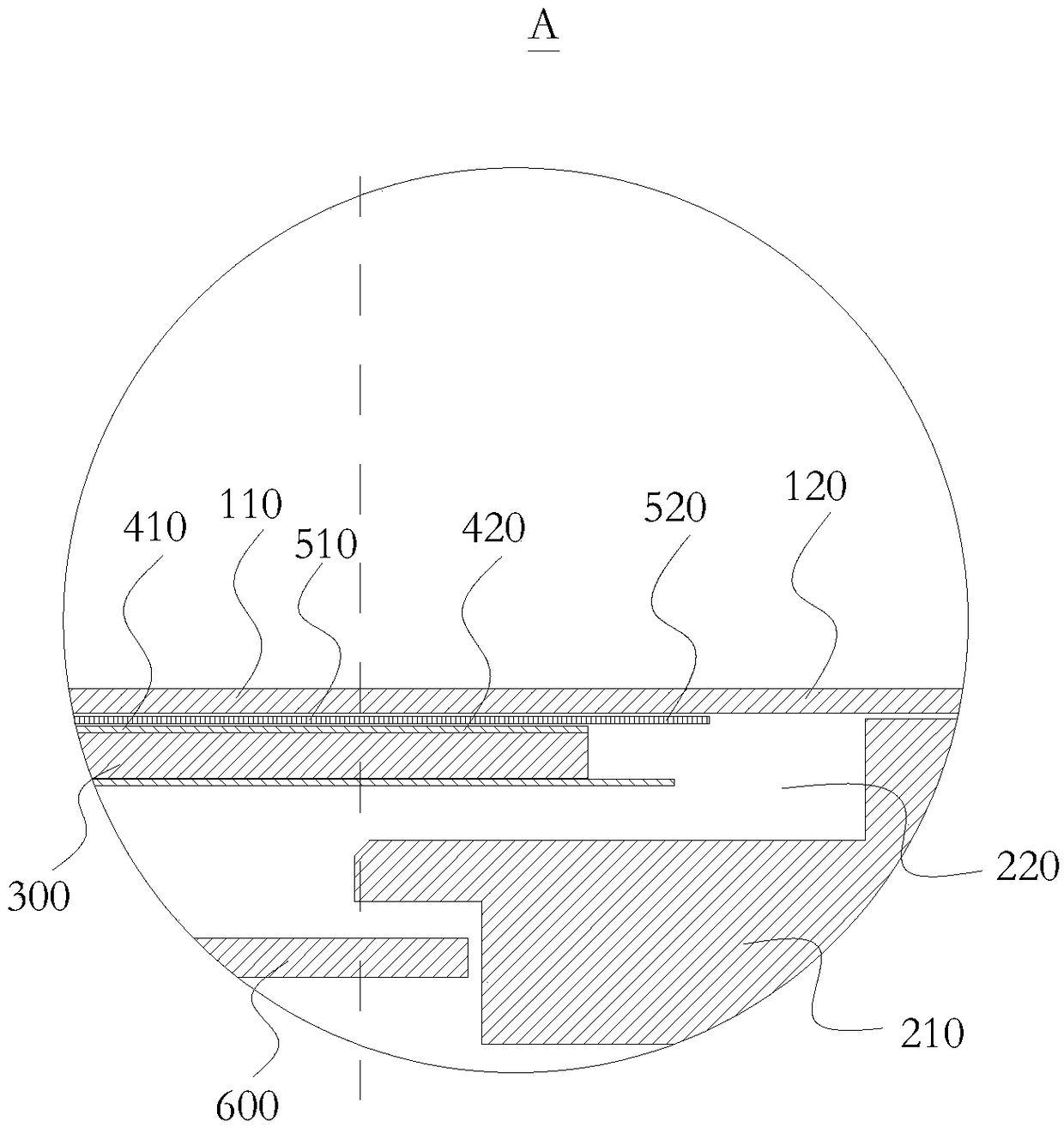
[0030] Such as Figure 1 to Figure 2 As shown, the embodiment of the present invention provides an electromagnetic touch structure, including a frame structure, and an electromagnetic screen structure disposed on the frame structure. The frame structure can provide support and fixation for the electromagnetic screen structure, and the electromagnetic screen structure can realize electromagnetic writing and control functions.

[0031] Specifically, the frame structure includes a flat metal backplane 100 and a frame structure 200 surrounding the metal backplane 100 . The above electromagnetic screen st...


PUM


Abstract

The invention discloses an electromagnetic touch structure, a side-in backlight display module and a display. The electromagnetic touch structure includes a frame structure and an electromagnetic screen structure disposed on the frame structure. The frame structure includes a tabular metal back plate and a side frame structure annularly arranged on the peripheral edge of the metal back plate. Theelectromagnetic screen structure includes a light guide plate and an electromagnetic film stacked between the metal back plate and the frame structure and a permanent magnet structure disposed on themetal back plate. The permanent magnet structure is located inside the frame structure, the permanent magnet structure is located between the electromagnetic film and the metal back plate, and the electromagnetic film is disposed above or below the light guide plate. By means of the technical scheme, electromagnetic signals shielded by the metal back plate can be strengthened, and touch or writingsignals can be normally identified.

Description

technical field [0001] The present invention relates to the technical field of display devices, in particular to an electromagnetic touch structure, a side-entry backlight display module and a display. Background technique [0002] In traditional technology, electromagnetic touch technology is applied to large-size touch all-in-one machines (above 40 inches), especially when the display module adopts a side-type backlight module design, due to the metal backlight of the display module The board is close to the electromagnetic antenna module, so that when electromagnetic writing is performed, the electromagnetic signal will be partially shielded by the metal backplane, resulting in a decrease in the magnetic flux of the electromagnetic coil of the electromagnetic antenna module, which will make it difficult to recognize the writing signal, which will make the whole machine When writing or controlling with the electromagnetic writing pen, there will be problems such as disconn...

Claims


Application Information

Patent Timeline
IPC IPC(8): G06F3/046G06F3/041
CPCG06F3/0412G06F3/0418G06F3/046
Inventor 邓芳光
Owner GUANGZHOU SHIYUAN ELECTRONICS CO LTD
Learn More