A current automatic cut-off device
An automatic cut-off and current technology, applied in the direction of circuits, electrical components, battery pack components, etc., can solve problems such as top cover movement, inability to resist battery vibration, and increased potential safety hazards
- Summary
- Abstract
- Description
- Claims
- Application Information
AI Technical Summary
Problems solved by technology
Method used
Image

Examples
Embodiment 1
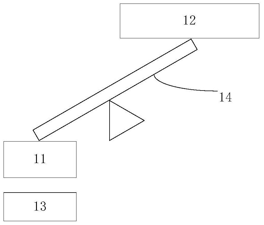
[0051] An embodiment of the present invention provides an automatic current cut-off device, referring to figure 1 As shown, the device includes:
[0052] The stress structure 11 and the power-off structure 12, the stress structure 11 is connected to the power-off structure 12, and the stress structure 11 is located on the exhaust hole 13;
[0053] When the internal pressure of the battery changes, the vent hole 13 releases gas and deforms, causing the stress structure 11 to move, and the movement of the stress structure 11 causes a state change of the power-off structure 12, thereby disconnecting the input and output current of the battery.
[0054] Preferably, the device also includes:
[0055] The lever structure 14 is connected to the stress structure 11 and the power-off structure 12 , the stress structure 11 moves, and the state of the power-off structure 12 changes through the lever structure 14 .
[0056] Preferably, the device also includes a limiting structure;
[...
Embodiment 2
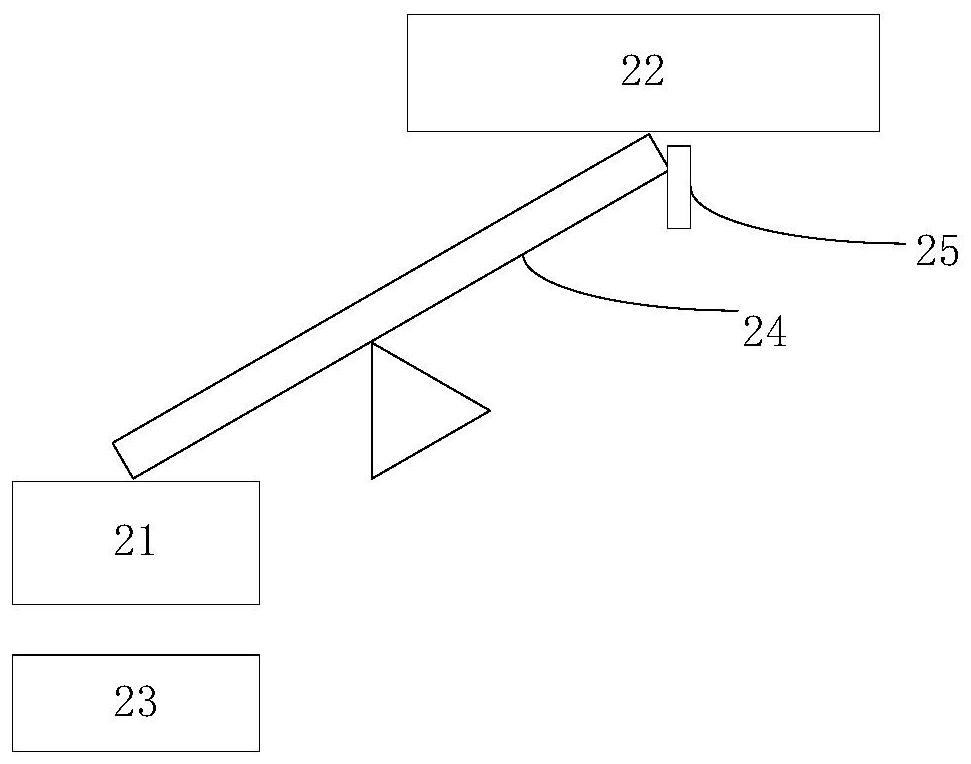
[0087] An embodiment of the present invention provides an automatic current cut-off device, referring to figure 2 As shown, the device includes:
[0088] The stress structure 21 and the power-off structure 22, the stress structure 21 is connected to the power-off structure 22, and the stress structure 21 is located on the exhaust hole 23;
[0089] When the internal pressure of the battery changes, the vent hole 23 releases gas and deforms, causing the stress structure 21 to move, and the movement of the stress structure 21 causes the state change of the power-off structure 22, thereby disconnecting the input and output current of the battery.
[0090] Specifically, after an abnormality occurs inside the battery and gas is generated, the row of vent holes 23 deforms and protrudes upwards, and exerts a force on the stress structure 21 along the direction of the round hole, so that the stress structure 21 moves along the round hole; the stress structure 21 is connected with the...
Embodiment 3
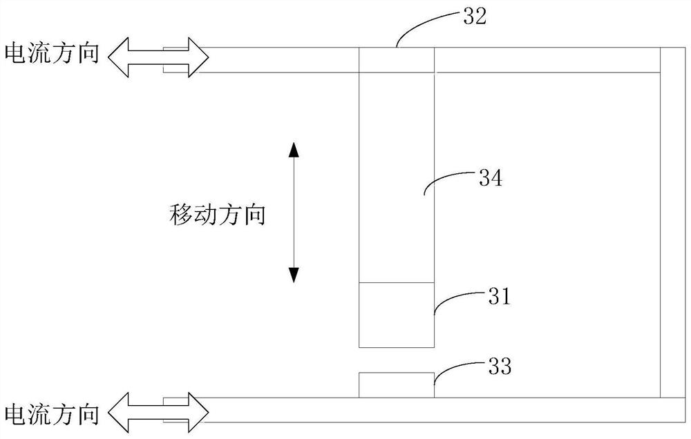
[0139] An embodiment of the present invention provides an automatic current cut-off device, referring to image 3 As shown, the device includes:
[0140] The stress structure 31 and the power-off structure 32, the stress structure 31 is connected to the power-off structure 32, and the stress structure 31 is located on the exhaust hole 33;
[0141] When the internal pressure of the battery changes, the vent hole 33 releases gas and deforms, causing the stress structure 31 to move, and the movement of the stress structure 31 causes the state of the power-off structure 32 to change, thereby disconnecting the input and output current of the battery. current loop
[0142] preferred,
[0143] The stress structure 31 and the power-off structure 32 are located in the same column 34, the upper part of the column is the power-off structure 32, the lower part of the column 34 is the stress structure 31, and the top of the power-off structure 32 is located in the current loop of the bat...
PUM
 Abstract
Description
Claims
Application Information
 - R&D
- Intellectual Property
- Life Sciences
- Materials
- Tech Scout
- Unparalleled Data Quality
- Higher Quality Content
- 60% Fewer Hallucinations
Browse by: Latest US Patents, China's latest patents, Technical Efficacy Thesaurus, Application Domain, Technology Topic, Popular Technical Reports.
© 2025 PatSnap. All rights reserved.Legal|Privacy policy|Modern Slavery Act Transparency Statement|Sitemap|About US| Contact US: help@patsnap.com