
Current automatic cut-off device applied to new energy battery

A technology that automatically cuts off batteries, is applied to battery components, circuits, electrical components, etc., and can solve problems such as failure to achieve safety protection, battery internal resistance drift, and increased potential safety hazards

Pending Publication Date: 2018-09-21
SUZHOU JUTIANHE METAL TECHNOLOGY CO LTD
View PDF0 Cites 0 Cited by
  • Summary
  • Abstract
  • Description
  • Claims
  • Application Information

AI Technical Summary

Problems solved by technology

[0004] However, in the process of using this technical solution, since the automatic current cut-off device is inside the battery, and there is no connection between the top cover and the aluminum cover plate, the top cover is prone to movement, resulting in drift of the internal resistance of the battery, and the battery cannot resist vibration. , It is easy to open the welding during the vibration of the battery, and it has never been unable to achieve effective safety protection
In addition, since the current automatic cut-off device is inside the battery, when the battery is abnormal, it is easy to contact the internal chemical solution and cause dangerous accidents such as explosion
Increase the possibility of battery explosion, but further increase the potential safety hazard

Method used


Image

  • Current automatic cut-off device applied to new energy battery

Examples


Embodiment 1

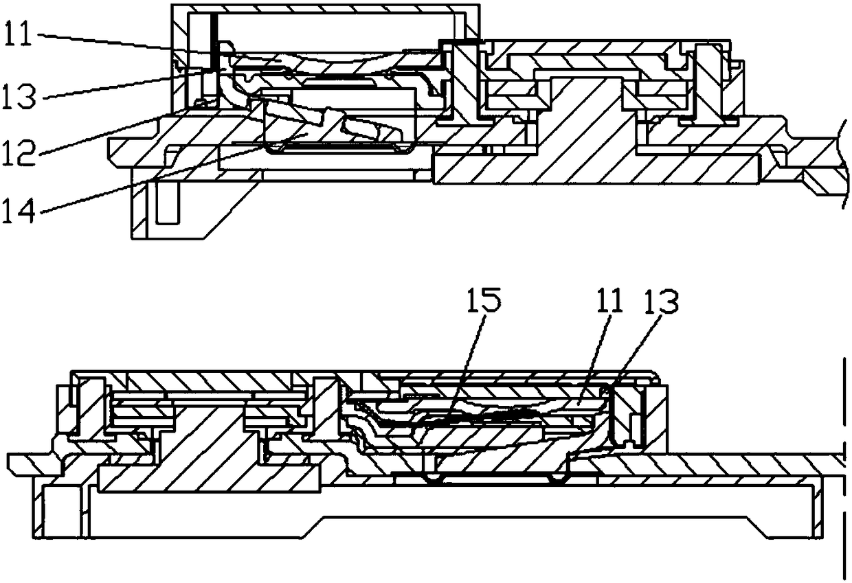
[0060] An embodiment of the present invention provides an automatic current cut-off device applied to new energy batteries, the device includes:

[0061] De-energized structure, stress structure and lever structure;

[0062] One end of the power-off structure is connected to the terminal board through an elastic component, and the elastic component has conductivity;

[0063] The middle part of the power-off structure includes a circular concave structure;

[0064] The stress structure is connected to the lever structure; the bottom surface of the stress structure is in contact with the exhaust hole; the part where the bottom surface of the power-off structure is in contact with the stress structure includes at least one elastic structure; the outer diameter of the stress structure is smaller than the inner diameter of the round hole where the exhaust hole is located;

[0065] The fulcrum of the lever structure is located on the inner bottom surface of the housing, one end of ...

Embodiment 2

[0077] An embodiment of the present invention provides an automatic current cut-off device applied to new energy batteries, the device includes:

[0078] De-energized structure, stress structure and lever structure;

[0079] One end of the power-off structure is connected to the terminal board through an elastic component, and the elastic component has conductivity;

[0080] The middle part of the power-off structure includes a circular concave structure;

[0081] The two wings of the power-off structure respectively include a strip-shaped concave structure; the inner diameter of the strip-shaped concave structure is larger than the inner diameter of the circular concave structure;

[0082] The stress structure is connected to the lever structure; the bottom surface of the stress structure is in contact with the exhaust hole; the outer diameter of the stress structure is smaller than the inner diameter of the circular hole where the exhaust hole is located;

[0083] The fulc...

Embodiment 3

[0113] An embodiment of the present invention provides an automatic current cut-off device applied to new energy batteries, the device includes:

[0114] De-energized structure, stress structure and lever structure;

[0115] One end of the power-off structure is connected to the terminal board through an elastic component, and the elastic component has conductivity; the embodiment of the present invention does not limit the specific flexible connection method.

[0116] The middle part of the power-off structure includes a circular concave structure; the embodiment of the present invention does not limit the area of ​​the device part where the circular concave structure is located. In practical applications, the material of the circular concave structure can be an elastic material , and part or all of the elastic material is a conductive material, and the embodiment of the present invention does not limit the specific material.

[0117] The two wings of the power-off structure...


PUM


Abstract

The embodiment of the invention provides a current automatic cut-off device applied to a new energy battery, and belongs to the field of battery accessories. The current automatic cut-off device applied to the new energy battery comprises a power-off structure, a stress structure and a lever structure; one end of the power-off structure is movably connected with a terminal plate; the middle part of the power-off structure comprises a round concave structure; each of two wing parts of the power-off structure comprises a strip-shaped concave structure; the inner diameter of the strip-shaped concave structure is more than the inner diameter of the round concave structure; the stress structure is connected with the lever structure; the bottom surface of the stress structure is contacted with avent hole; the outer diameter of the stress structure is less than the inner diameter of a round hole in which the vent hole is formed; the supporting point of the lever structure is positioned on the inner bottom surface of a shell; one end of the lever structure is connected with the upper surface of the stress structure and the other end of the lever structure is connected with a limiting structure. The current automatic cut-off device is arranged outside the battery, so that effective safety protection is realized. The possibility of battery explosion is reduced and the safety is improved.

Description

technical field [0001] The invention relates to the field of battery accessories, in particular to an automatic current cut-off device applied to new energy batteries. Background technique [0002] Due to its excellent characteristics, lithium batteries have gradually been accepted by the market and developed rapidly. However, during the use of lithium batteries, there are unsafe problems such as battery explosions when the batteries are overcharged or short-circuited. [0003] In order to solve the above problems, the technical solution provided by the prior art is to connect the CID (Current Interrupt device, current automatic cut-off device) combination cover plate and the aluminum cover plate together by sealing welding as the current automatic cut-off device, and install it inside the battery. [0004] However, in the process of using this technical solution, since the automatic current cut-off device is inside the battery, and there is no connection between the top co...

Claims


Application Information

Patent Timeline
Patent Type & Authority Applications(China)
IPC IPC(8): H01M2/34H01M50/579
CPCH01M50/579H01M50/578Y02E60/10
Inventor 邱实金炫中
Owner SUZHOU JUTIANHE METAL TECHNOLOGY CO LTD
Learn More