Electric connector for achieving locking and unlocking functions through push rod

A technology of electrical connectors and push rods, which is applied in the direction of connection and connection device components, circuits, etc., can solve the problems of unstable structure, large insertion force, and difficulty in pressing the elastic arm, so as to achieve the advantages of easy operation and improved stability Effect

Pending Publication Date: 2018-10-16
翊腾电子科技(昆山)有限公司
View PDF0 Cites 4 Cited by
  • Summary
  • Abstract
  • Description
  • Claims
  • Application Information

AI Technical Summary

Problems solved by technology

However, there are many shortcomings in this existing locking method, and it is rarely used anymore.
For example: this lock method has a large insertion force; the structure is not stable enough, it is easy to i

Method used


Image

  • Electric connector for achieving locking and unlocking functions through push rod
  • Electric connector for achieving locking and unlocking functions through push rod
  • Electric connector for achieving locking and unlocking functions through push rod

Examples


Embodiment Construction

[0050] The following description of the embodiments refers to the accompanying drawings to illustrate specific embodiments in which the invention may be practiced. The directional terms mentioned in the present invention, such as "up", "down", "front", "back", "left", "right", "top", "bottom", etc., are only for reference to the attached drawings. direction. Therefore, the directional terms used are used to illustrate and understand the present invention, but not to limit the present invention.

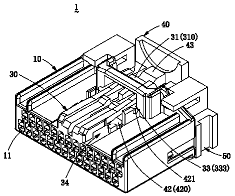
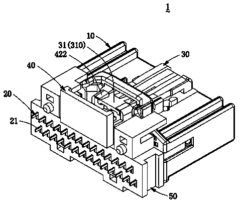
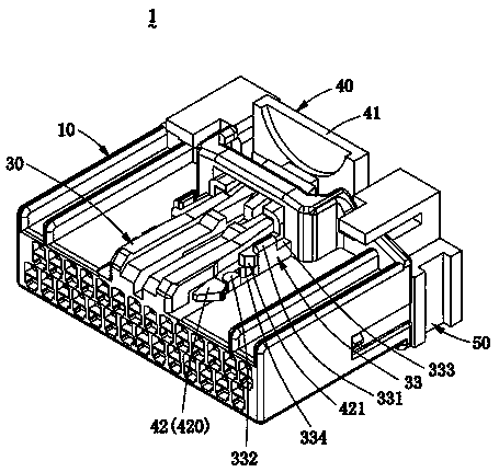
[0051] Please refer to Figure 1 to Figure 6 As shown, the electrical connector 1 of the present invention includes an insulating housing 10, a plurality of conductive terminals 20 installed in the insulating housing 10, a locking device 30 arranged on the top surface of the insulating housing 10, and a The push rod 40 movably mounted on the insulating housing 10 can activate the locking device 30 . The electrical connector 1 of the present invention can use the push rod 40 to touc...


PUM


Abstract

The invention discloses an electric connector for achieving locking and unlocking functions through a push rod. The electric connector comprises an insulating shell, a plurality of conducting terminals arranged in the insulating shell, a locking device arranged on the top face of the insulating shell, and the push rod movably installed on the top face of the insulating shell. According to the electric connector, the locking device is started by pushing the push rod forwards, a cantilever of the locking device is forced to drive a convex buckle to ascend, and therefore the electric connector issafely locked to a butt joint connector. When disconnection is needed, the push rod can be pulled backwards, the cantilever is forced to drive the convex buckle to descend, then the locking device isrestored to the original position, and therefore the electric connector can be pulled out quickly. The electric connector is safe and effective in the mode that the push rod is used for locking and unlocking.

Description

technical field [0001] The invention relates to the technical field of connectors, in particular to an electrical connector that utilizes a push rod to realize locking and unlocking functions. Background technique [0002] Usually, a locking device is provided on the two docked plug connectors and socket connectors to prevent the two electrical connectors from being loosened due to external force after docking, so as to ensure the reliability and safety of the mechanical connection between the two sex. [0003] The common locking method is to set the elastic arm on the plug connector, just like the previous network interface (RJ45) design, in the process of inserting the socket connector, the elastic arm is hard squeezed to make it yield and buckle in In the socket connector, thus completing the mating action. But there are many shortcomings in this existing locking mode, seldom adopt again. For example: this locking method has a large insertion force; the structure is no...

Claims


Application Information

Patent Timeline
IPC IPC(8): H01R13/633H01R13/639
CPCH01R13/6335H01R13/639
Inventor 涂海文张浩丁树林袁明高
Owner 翊腾电子科技(昆山)有限公司
Why Eureka
Try Eureka