Surface-mounted permanent magnet motor rotor and motor

A permanent magnet motor, surface technology, applied in the direction of magnetic circuit rotating parts, magnetic circuits, electromechanical devices, etc., can solve the problems of increasing the length of the stator and rotor air gap, reducing the performance of the motor, increasing the weight of the motor, etc. The effect of equivalent air gap length, improving utilization, and reducing motor weight

Inactive Publication Date: 2018-10-16
NANJING UNIV OF SCI & TECH +1
View PDF9 Cites 2 Cited by
  • Summary
  • Abstract
  • Description
  • Claims
  • Application Information

AI Technical Summary

Problems solved by technology

[0004] The purpose of the present invention is to provide a surface type permanent magnet motor rotor and motor to solve the problem that using a sheath in the prior art will increase the air gap length between the stator and the rotor, increase the weight of the motor, reduce the performance of the motor, and use filling Easy to cause permanent magnet loosening

Method used


Image

  • Surface-mounted permanent magnet motor rotor and motor
  • Surface-mounted permanent magnet motor rotor and motor
  • Surface-mounted permanent magnet motor rotor and motor

Examples


Embodiment approach 1

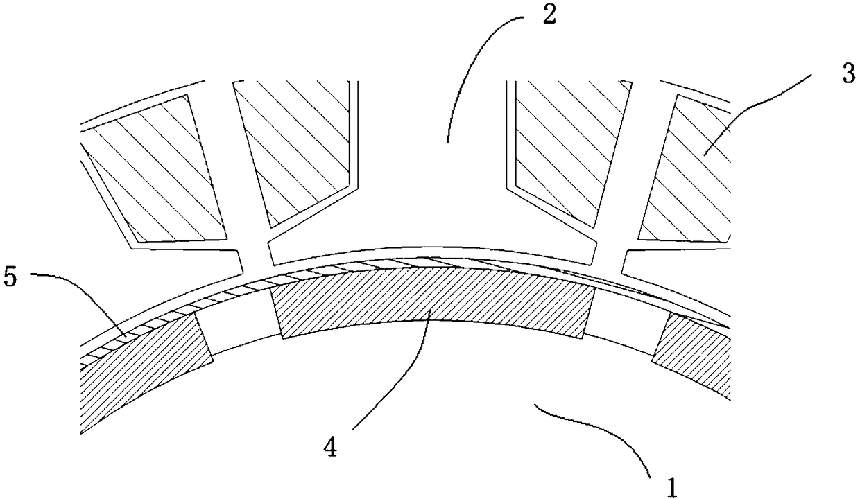
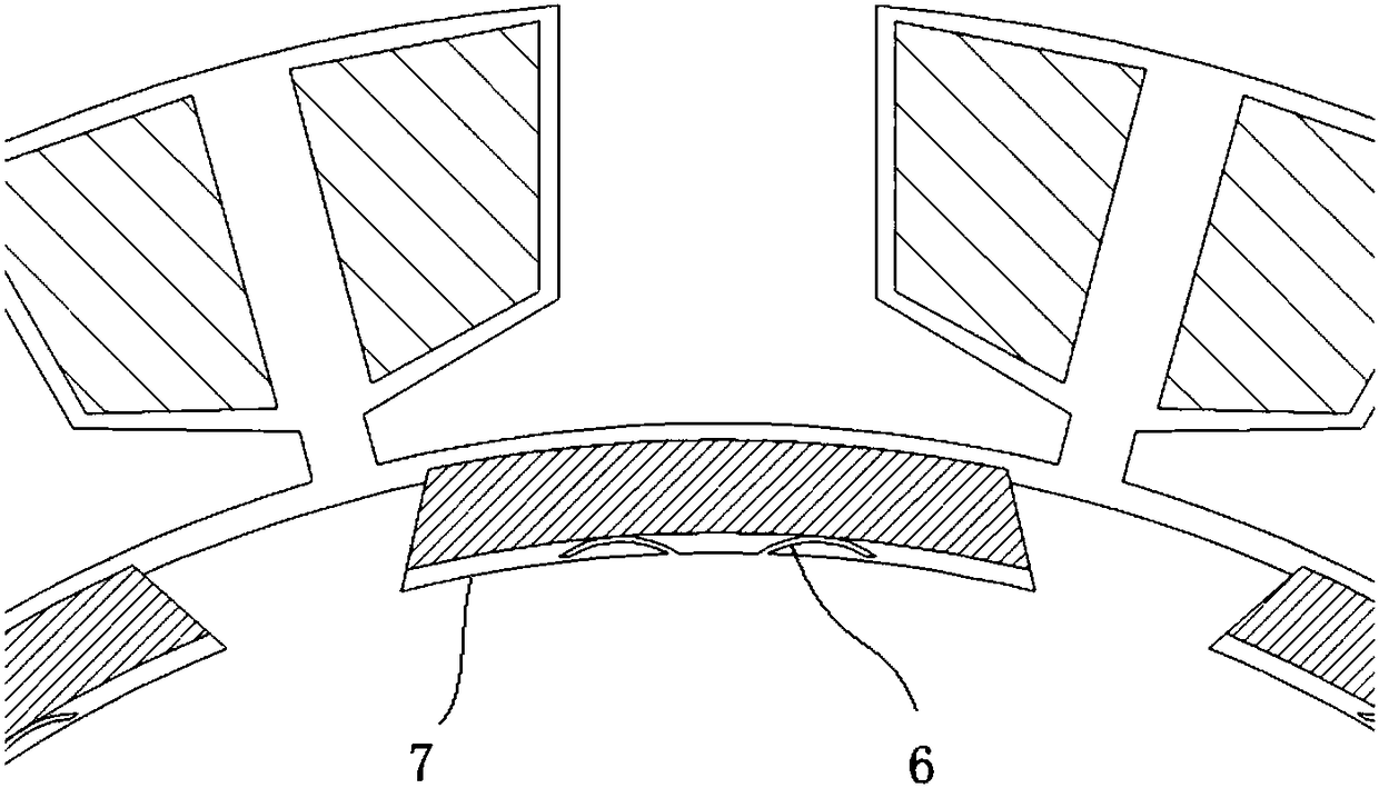
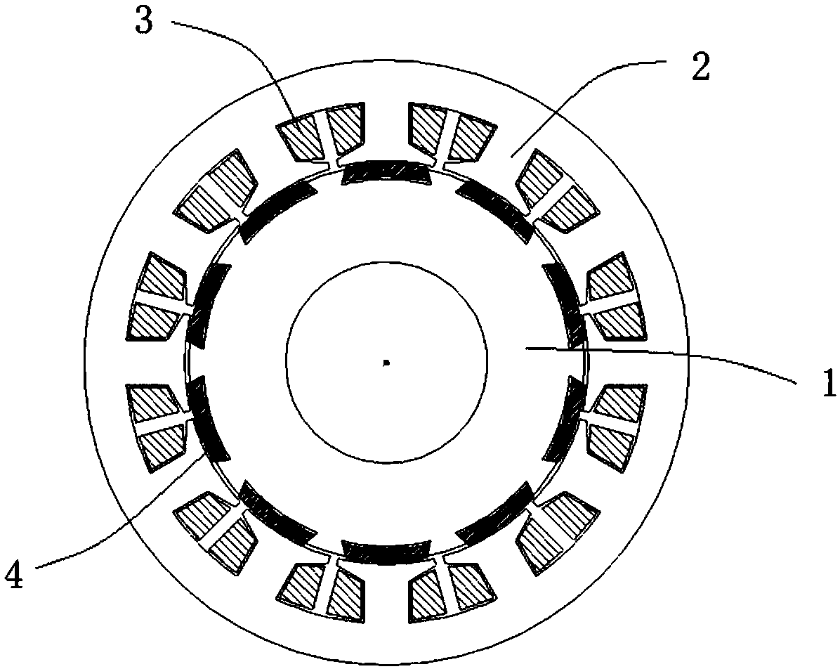
[0026] figure 2 It is a working diagram of the elastic sheet in this embodiment, image 3 It is a sectional view of the surface permanent magnet motor of this embodiment. The rotor of the surface permanent magnet motor in this embodiment includes a rotor body, the outer surface of the rotor body has a permanent magnet groove configured with permanent magnets 4, the permanent magnet groove adopts a dovetail groove structure, and more than one groove with the same width is left on the bottom edge of the permanent magnet groove. The elastic sheet 6 is integrally formed with the permanent magnet slot, one end is connected to the bottom edge 7 of the permanent magnet slot, and the other end is disconnected from the bottom edge of the permanent magnet slot to be in a freely movable state.

[0027] The elastic pieces 6 are arc-shaped, and the elastic pieces 6 are arranged side by side, and the directions of the free ends of every two adjacent elastic pieces 6 are opposite.

[0028...

Embodiment approach 2

[0031] Figure 5 It is a working schematic diagram of the elastic sheet in this embodiment. In this embodiment, the elastic piece 6 is polygonal, and preferably adopts a trapezoidal structure, wherein the top edge of the trapezoid is attached to the bottom of the permanent magnet 4 .

[0032] Other structures of this embodiment are the same as those of Embodiment 1.

Embodiment approach 3

[0034] like Image 6 As shown, the permanent magnet slots in this embodiment adopt T-shaped slots, and other structures are the same as those in Embodiment 1.


PUM


Abstract

The invention discloses a surface-mounted permanent magnet motor rotor and a motor, wherein the motor rotor comprises a rotor body; the outer surface of the rotor body is provided with a permanent magnet groove for arranging a permanent magnet; elastic piece is arranged on the bottom edge and / or side edge of the permanent magnet groove; one end of the elastic piece is connected with the groove edge in a whole; and the other end of the elastic piece is disconnected from the groove edge to be in a freely movable state. When the permanent magnet is mounted, the permanent magnet is extruded intothe permanent magnet groove; the elastic piece is extruded; the distance between the free moving end of the elastic piece and the bottom edge of the groove is reduced; elastic deformation is generated; and the permanent magnet is tightly pressed into the permanent magnet groove by elastic forcegenerated by elastic deformation of the elastic piece. According to the surface-mounted permanent magnetmotor rotor and motor, the permanent magnet can be conveniently fixed; the use of the sheath is removed; the use of the filler is reduced or even eliminated; vibration borne by the permanent magnet is reduced; and demagnetization of the permanent magnet is avoided.

Description

technical field [0001] The invention relates to the technical field of motors, in particular to a surface type permanent magnet motor rotor and a motor. Background technique [0002] figure 1 It is a partial sectional view of an existing surface permanent magnet motor, and the surface permanent magnet motor is mainly composed of a stator and a rotor as a whole. The stator is fixed and is composed of a stator body 2 and a winding 3. The stator body 2 is formed by lamination of stator laminations, and the winding 3 is wound on the teeth of the stator body. The rotor rotates and is composed of a rotor body 1 and a permanent magnet 4. The rotor body 1 is formed by stacking rotor laminations, and the permanent magnet 4 is fixed on the outer surface of the rotor body. [0003] In existing surface electronics, a layer of sheath 5 is sheathed on the outer layer of the permanent magnet, and fillers such as resin and glue are used in combination to fix the permanent magnet 4 on the ...

Claims


Application Information

Patent Timeline
Patent Type & Authority Applications(China)
IPC IPC(8): H02K1/27
CPCH02K1/278
Inventor 殷德军张冰丁佐蓬张凯
Owner NANJING UNIV OF SCI & TECH
Why Eureka
Try Eureka