High-speed power system
A power system and high-speed technology, applied in the direction of electrical components, electromechanical devices, etc., can solve problems such as power scale and efficiency barriers
- Summary
- Abstract
- Description
- Claims
- Application Information
AI Technical Summary
Problems solved by technology
Method used
Image

Examples
Embodiment 1
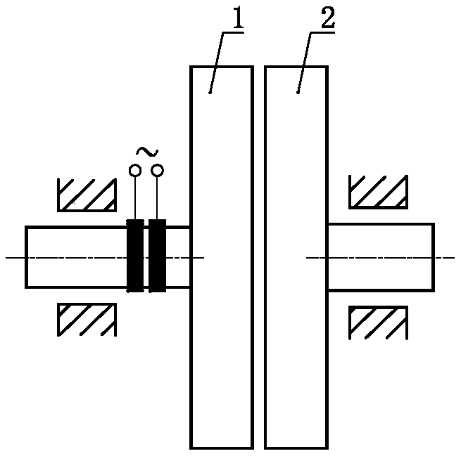
[0031] A high-speed powertrain such as figure 1 As shown, it includes a rotating structure A 1 and a rotating structure B 2, a coil is arranged on the rotating structure A 1, and the coil forms a rotating magnetic field on the rotating structure A 1, and the rotating structure A 1 A magnetic zone is set on B2, and the rotating magnetic field and the magnetic zone are mutually magnetically arranged.
Embodiment 2
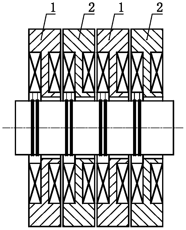
[0033] A high-speed powertrain such as figure 2 As shown, it includes a rotating structure A 1 and a rotating structure B 2, the rotating structure A 1 and the rotating structure B 2 are arranged alternately, a coil A is arranged on the rotating structure A 1, and the coil A forms a rotating magnetic field on the rotating structure A1, and sets a coil B on the rotating structure B2, and the coil B forms a rotating magnetic field on the rotating structure B2, and the adjacent rotating The structure A 1 and the rotating structure B 2 are mutually magnetically arranged, wherein two rotating structures A 1 and two rotating structures B 2 are arranged alternately.
[0034] As a changeable implementation mode, in Example 2 of the present invention, two, three, four, five, six, seven, eight, nine, ten, and eleven , Twelve or more said rotating structures A 1 and said rotating structures B 2 arranged alternately.
Embodiment 3
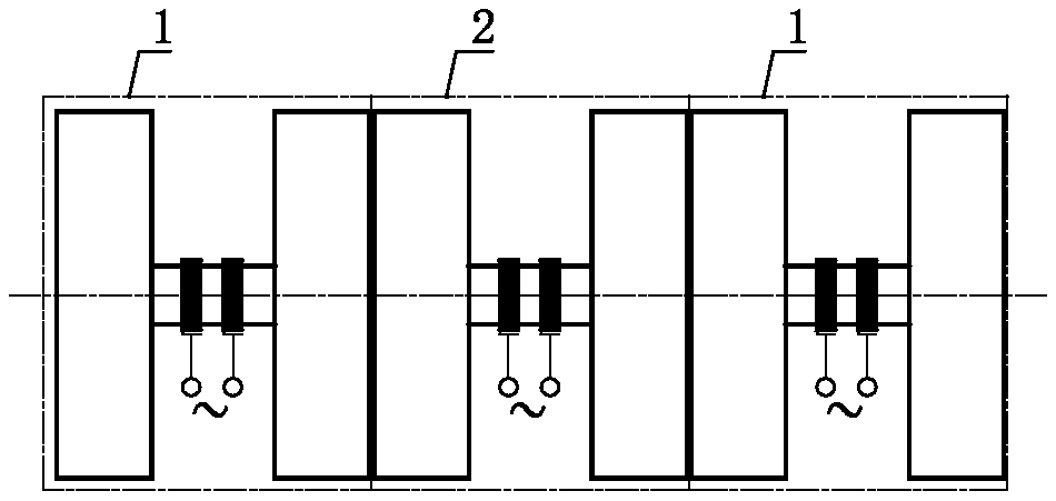
[0036] A high-speed powertrain such as image 3 As shown, it includes a rotating structure A 1 and a rotating structure B 2, the rotating structure A 1 and the rotating structure B 2 are alternately arranged, and the coil A is arranged on the rotating structure A 1 1 and coil A 2 , the coil A 1 and the coil A 2 A rotating magnetic field with an opposite rotation direction is formed on the rotating structure A1, and a coil B is installed on the rotating structure B2 1 and coil B 2 , the coil B 1 and the coil B 2 A rotating magnetic field with an opposite rotation direction is formed on the rotating structure body B2, and the adjacent rotating structure body A1 and the rotating structure body B2 are mutually magnetically arranged.
[0037] As an alternative implementation, Embodiment 3 of the present invention can also selectively choose to make the coil A 1 and the coil A 2 A rotating magnetic field with the same rotation direction is formed on the rotating structure A1...
PUM
 Abstract
Description
Claims
Application Information