
Oil cylinder disassembly machine

A technology for disassembling and assembling machines and oil cylinders, which is applied in metal processing equipment, metal processing, manufacturing tools, etc., can solve the problems of affecting disassembly and assembly, axial movement of the cylinder body, and high requirements on coaxiality, and achieve the effect of improving efficiency.

Active Publication Date: 2021-04-23
PANZHIHUA UNIV
View PDF1 Cites 1 Cited by
  • Summary
  • Abstract
  • Description
  • Claims
  • Application Information

AI Technical Summary

Problems solved by technology

When installing the piston rod, the coaxiality of the cylinder body and the piston rod is very high. The above oil cylinder dismounting device uses 4 arc-shaped clamping plates to fix the piston rod and the cylinder body. It is difficult to ensure the cylinder body and the piston rod. The centerline is in the center of the positioning through hole, so the concentricity is not guaranteed
In addition, since the elastic pads are arranged on the inner side of the clamping plates, the deformation of the elastic pads on each clamping plate cannot be controlled, further increasing the coaxiality error
When the piston rod is pulled out or inserted into the cylinder, it is necessary to apply a large pulling or pushing force to the piston rod. After the force is transmitted to the cylinder, unless the clamping plate exerts a particularly large pressure on the cylinder, the cylinder is likely to be shafted. to move, affect the normal disassembly

Method used


Image

  • Oil cylinder disassembly machine
  • Oil cylinder disassembly machine
  • Oil cylinder disassembly machine

Examples


Embodiment Construction

[0029] The present invention will be further described below in conjunction with the accompanying drawings and embodiments.

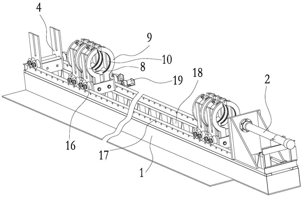
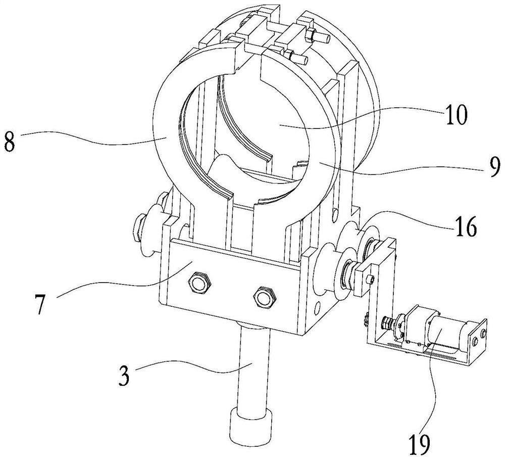
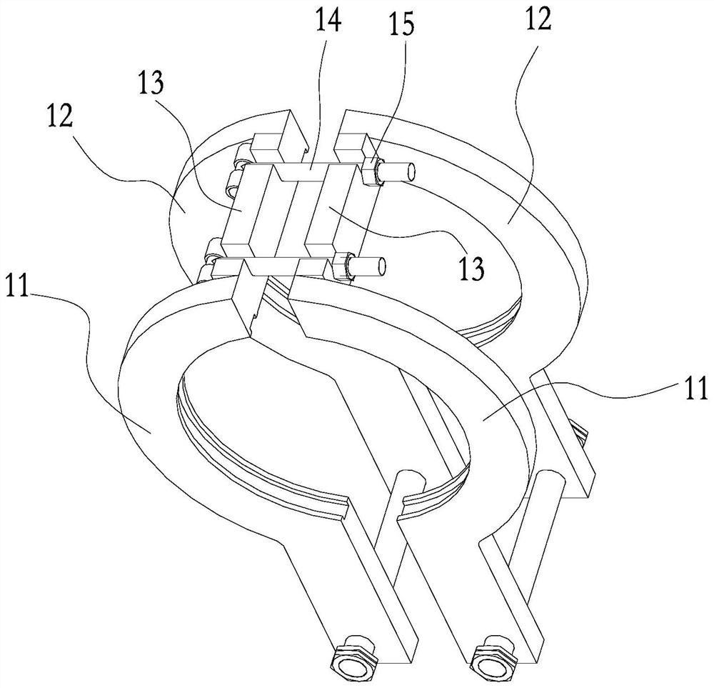
[0030] Such as Figure 1 to Figure 10 As shown, the oil cylinder dismounting machine of the present invention includes a base 1, and the base 1 is provided with a push-pull power mechanism 2 and a cylinder clamping mechanism,

[0031] The base 1 is provided with a lifting mechanism 3, and the cylinder clamping mechanism is installed on the lifting mechanism 3;

[0032] The base 1 is provided with a positioning seat 4, the positioning seat 4, the cylinder body clamping mechanism and the push-pull power mechanism 2 are distributed sequentially, and the positioning seat 4 is provided with a detachable tooling 5 for removing the baffle or installing a baffle Tooling 6, specifically, when removing the piston rod, use the tooling 5 for removing the baffle, and when installing the piston rod, remove the tooling 5 for removing the baffle, and install the tooli...


PUM


Abstract

The invention discloses an oil cylinder dismounting machine, comprising a machine base, a push-pull power mechanism and a cylinder clamping mechanism are arranged on the said machine base, a lifting mechanism is arranged on the said machine base, and the cylinder clamping mechanism is installed On the lifting mechanism; the machine base is provided with a positioning seat, the positioning seat, the cylinder body clamping mechanism and the push-pull power mechanism are distributed in sequence, and the positioning seat is provided with a detachable tool for removing the baffle or a tool for installing the baffle . Install the cylinder clamping mechanism on the lifting mechanism. After the cylinder clamping mechanism clamps the cylinder well, the height of the cylinder can be adjusted through the lifting mechanism so that the centers of the cylinder, piston rod, and push-pull power mechanism are at the same height , to ensure good assembly accuracy. By setting the positioning seat and removing the baffle tooling (or installing the baffle tooling), the removal of the baffle tooling and the installation of the baffle tooling can play a role in blocking the axial movement of the cylinder, so that the cylinder remains stable and is conducive to smooth disassembly. installed to improve efficiency.

Description

technical field [0001] The invention relates to the field of hydraulic equipment manufacturing equipment, in particular to an oil cylinder disassembly machine. Background technique [0002] Hydraulic systems are widely used in modern engineering, and the repair and maintenance of oil cylinders have become an important part of hydraulic systems. Due to the different conditions of use of hydraulic cylinders, various cylinder failures will occur, such as difficult disassembly of the cylinder, and jamming of the piston and cylinder due to deformation, impurities and other factors. The traditional manual disassembly and assembly is labor-intensive, inefficient, poor in quality, and to a certain extent will cause damage to some components of the cylinder. [0003] The utility model patent with the application number 201721007500.3 discloses an oil cylinder disassembly device, including a frame, on which a mounting seat is provided, and a mounting seat through hole for placing the...

Claims


Application Information

Patent Timeline
Patent Type & Authority Patents(China)
IPC IPC(8): B23P19/027
CPCB23P19/027
Inventor 谭兴强
Owner PANZHIHUA UNIV
Learn More