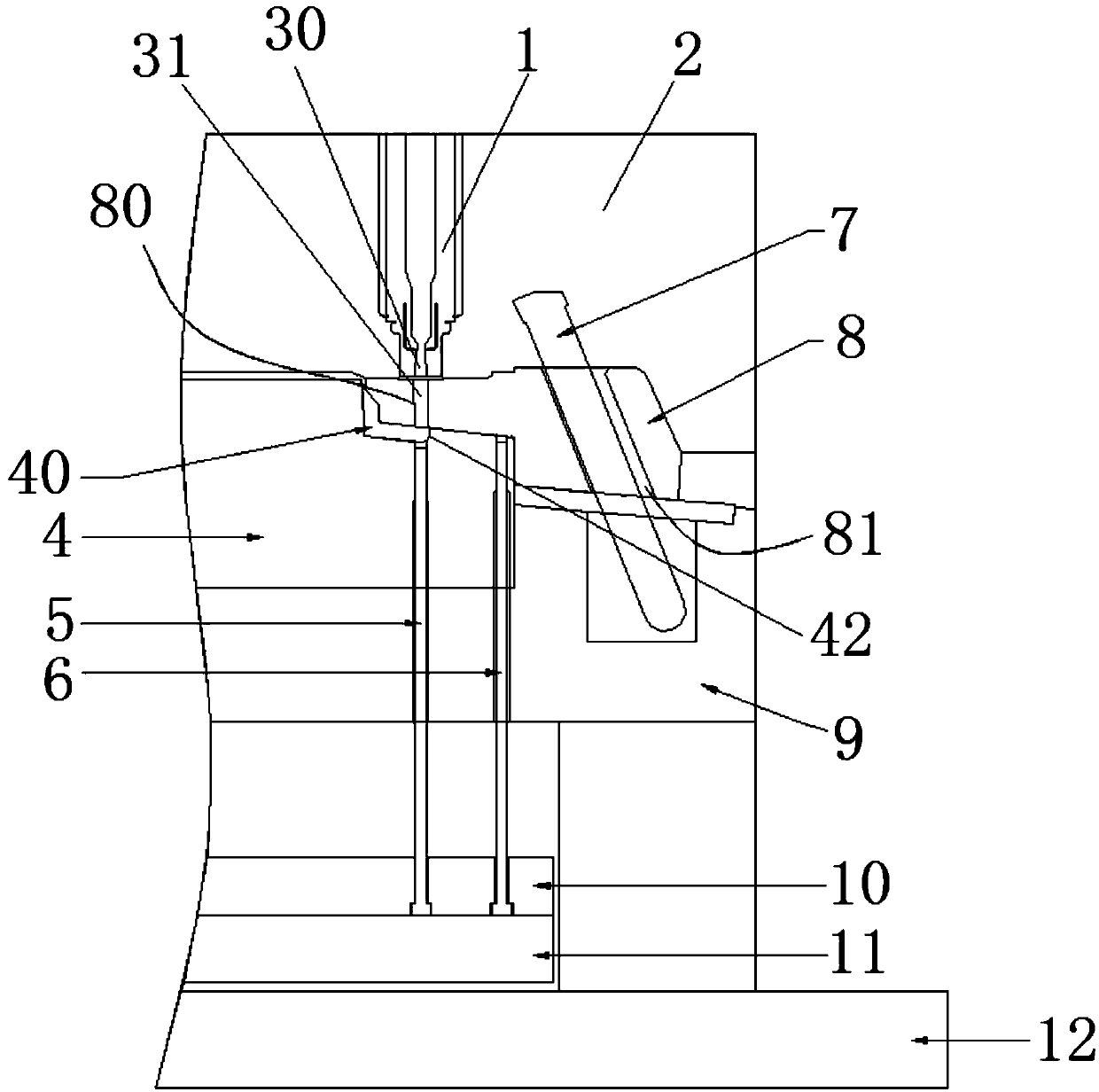
Structure allowing glue to be injected from the bottom of sliding block

A sliding block and glue feeding technology, applied in the field of injection molds, can solve the problems of increased material cost, excessively long runners, mold expansion, etc., and achieve the effect of saving energy consumption and cost, reducing material cost, and reducing injection pressure.

Pending Publication Date: 2018-10-19
QINGDAO HUATAO AUTOMOBILE MOLD
View PDF0 Cites 2 Cited by
  • Summary
  • Abstract
  • Description
  • Claims
  • Application Information

AI Technical Summary

Problems solved by technology

[0002] There are mainly two existing technical solutions, one is that the glue inlet point is directly set on the product surface, which will affect the integrity of the product appearance
The other is that it is necessary to sacrifice the best glue-feeding position and choose a less-than-ideal glue-feeding position, which will cause various problems in the injection molding process, suc

Method used


Image

  • Structure allowing glue to be injected from the bottom of sliding block

Examples


Example Embodiment

[0010] The present invention will be further described below in conjunction with the drawings and embodiments:

[0011] In the present invention, unless otherwise clearly specified and limited, the terms "installed", "connected", "connected", "fixed" and other terms should be understood in a broad sense, for example, it may be a fixed connection or a detachable connection , Or integrated; it can be directly connected, or indirectly connected through an intermediate medium, it can be the internal communication between two elements or the interaction between two elements. For those of ordinary skill in the art, the specific meanings of the above terms in the present invention can be understood according to specific circumstances.

[0012] In the present invention, unless otherwise clearly defined and defined, the "on" or "under" of the first feature of the second feature may include direct contact between the first and second features, or may include the first and second features No...


PUM


Abstract

The invention relates to the field of injection molds, in particular to a structure allowing glue to be injected from the bottom of a sliding block. The structure comprises a hot nozzle, an upper moving plate, a die core, a first ejector rod, a second ejector rod, an inclined guide column, the sliding block, a mold plate, an upper ejector plate, a lower ejector plate and a bottom plate. By the adoption of the structure, the integrity of product appearance can be ensured, and smooth filling is ensured as well; the injection molding pressure is greatly reduced, and the problems of mold expansion, deformation, material shortage and the like caused by excessive pressure are avoided; the energy consumption and cost are saved, a material path is shorter, and the material cost is reduced; and a gate is formed in the non-appearance surface without affecting the appearance quality of the product.

Description

technical field [0001] The invention relates to the field of injection molds, in particular to a structure for feeding glue from the bottom of a slider. Background technique [0002] There are mainly two kinds of existing technical solutions, one is that the glue feed point is directly set on the product surface, which will affect the integrity of the product appearance. The other is that it is necessary to sacrifice the best glue-feeding position and choose a less-than-ideal glue-feeding position, which will cause various problems in the injection molding process, such as mold swelling, deformation, and material shortage caused by excessive pressure. These problems may require the selection of a larger-sized injection molding machine, or it may take several process adjustments to reduce the pressure. This is undoubtedly a loss of equipment energy consumption and labor costs. In addition, the flow path is too long, which increases the material cost. Contents of the invent...

Claims


Application Information

Patent Timeline
IPC IPC(8): B29C45/27B29C45/33B29C45/40
CPCB29C45/27B29C45/2756B29C45/332B29C45/401B29C2045/0027
Inventor 曲婷婷孙伟孙志成张健塘
Owner QINGDAO HUATAO AUTOMOBILE MOLD
Why Eureka
Try Eureka