Method of preparing functional ceramic part of complex structure by powder injection molding

A technology for powder injection molding and functional ceramics, applied in ceramic molding machines, manufacturing tools, metal processing equipment, etc., can solve the problems of increased powder cost, product performance impact, poor shape retention, etc., to improve product performance and reduce product performance. Quality, the effect of reducing the amount of machining

Active Publication Date: 2019-11-22
CHANGZHOU GIAN TECH
View PDF22 Cites 14 Cited by
  • Summary
  • Abstract
  • Description
  • Claims
  • Application Information

AI Technical Summary

Problems solved by technology

[0003] At present, the preparation method of functional ceramic parts is mainly prepared by powder compression molding. The disadvantages are: 1) The green body obtained by compression molding has low dimensional accuracy and simple structure, and a large amount of machining is required to ensure the structure and quality of the product. Dimensional accuracy; 2) Affected by the characteristics of the compression molding method, the density/density of the product along the thickness direction is inconsistent, resulting in affected product performance, and the product has a large amount of deformation during the sintering process; 3) Compression molding has a greater impact on The fluidity requirement of the ceramic powder is higher, that is, the particle size of the powder needs to be coarser, usually D 50 ≥4μm, therefore, the sintering temperature of the product needs to be greatly increased
In summary: Functional ceramics prepared by pressing molding have poor control over product size, structural complexity, and product size consistency, which is not conducive to the batch preparation of complex structural functional ceramics
[0004] Although som

Method used


Image

  • Method of preparing functional ceramic part of complex structure by powder injection molding
  • Method of preparing functional ceramic part of complex structure by powder injection molding

Examples


Example Embodiment

[0030] (Example 1)

[0031] When preparing an alumina ceramic product with a product wall thickness of 2mm through powder injection molding, the present invention includes the following steps:

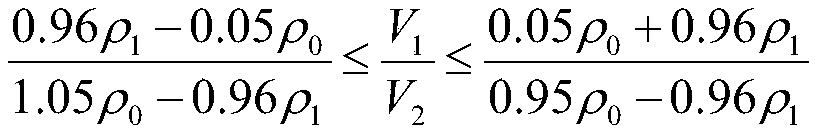
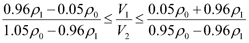
[0032] S1. Feed preparation: uniformly mix the alumina ceramic powder and the binder to form the feed, the volume of the alumina ceramic powder V 1 And binder volume V 2 The ratio is Tap density of alumina ceramic powder ρ 1 1.82g / cm 3 ,Theoretical density of alumina ceramic powder ρ 0 3.96g / cm 3 ; Particle size D of alumina ceramic powder 50 For: 2.3μm;

[0033] S2, injection molding: the feed prepared in step S1 is placed in a powder injection molding machine, and injected into the mold cavity under the conditions of 80-200MPa injection pressure and 160-200°C injection temperature to form an injection blank;

[0034] S3. Degreasing: The injection billet prepared in step S2 is catalytically degreasing to form a catalytic degreasing billet; the catalyst is nitric acid. The specific degreasing ...

Example Embodiment

[0043] (Example 2)

[0044] When preparing an alumina ceramic product with a product wall thickness of 4mm through powder injection molding, the present invention includes the following steps:

[0045] S1. Feed preparation: uniformly mix the alumina ceramic powder and the binder to form the feed, the volume of the alumina ceramic powder V 1 And binder volume V 2 The ratio is The tap density ρ1 of alumina ceramic powder is 1.62g / cm 3 , The theoretical density of alumina ceramic powder ρ0 is 3.96g / cm 3 ; Particle size D of alumina ceramic powder 50 For: 0.62μm;

[0046] S2, injection molding: the feed prepared in step S1 is placed in a powder injection molding machine, and injected into the mold cavity under the conditions of 80-200MPa injection pressure and 160-200°C injection temperature to form an injection blank;

[0047] S3. Degreasing: The injection billet prepared in step S2 is catalytically degreasing to form a catalytic degreasing billet; the catalyst is nitric acid. The specif...

Example Embodiment

[0056] (Example 3)

[0057] When preparing a zirconia ceramic product with a product wall thickness of 3.5 mm through powder injection molding, the present invention includes the following steps:

[0058] S1. Feed preparation: uniformly mix the zirconia ceramic powder and the binder to form the feed, the volume of the zirconia ceramic powder V 1 And binder volume V 2 The ratio is Tap density of zirconia ceramic powder ρ 1 2.89g / cm 3 ,Theoretical density of zirconia ceramic powder ρ 0 6.01g / cm 3 ; Particle size D of zirconia ceramic powder 50 Is: 1.85μm;

[0059] S2, injection molding: the feed prepared in step S1 is placed in a powder injection molding machine, and injected into the mold cavity under the conditions of 80-200MPa injection pressure and 160-200°C injection temperature to form an injection blank;

[0060] S3. Degreasing: The injection billet prepared in step S2 is catalytically degreasing to form a catalytic degreasing billet; the catalyst is nitric acid. The specific deg...


PUM

PropertyMeasurementUnit
Particle sizeaaaaaaaaaa
Tap densityaaaaaaaaaa
Theoretical densityaaaaaaaaaa

Abstract

The invention relates to a method of preparing a functional ceramic part of complex structure by powder injection molding. The method is characterized by comprising the following steps: S1, feed preparation: uniformly mixing functional ceramic powder with an adhesive to form a feed; S2, injection moulding: putting the feed prepared in the S1 in a powder injection moulding machine, and injecting the feed into a mold cavity under conditions of an injection pressure of 80-200 MPa and an injection temperature of 160-200 DEG C to form an injection blank; S3, degreasing: catalytically degreasing theinjection blank prepared in the S2 to form a catalytically degreased blank; S4, thermal degreasing: thermally degreasing the catalytically degreased blank prepared in the S3 to obtain a thermally degreased blank; and S5, sintering: putting the thermally degreased blank prepared in the S4 in a sintering furnace, and sintering the thermally degreased blank in an air atmosphere to obtain a sinteredblank. By setting a volume ratio range of the functional ceramic powder and the adhesive, the functional ceramic powder can be totally coated by the adhesive, so that the flawless injection blank is more easily obtained.

Description

technical field [0001] The invention relates to the field of preparation of a ceramic part with a complex structure and function, in particular to a method for preparing a ceramic part with a complex structure and function by powder injection molding. Background technique [0002] Because of their special dielectric properties, temperature characteristics, and extremely high corrosion resistance, strength, and hardness, ceramic materials are widely used in some parts that need to achieve special electromagnetic functions. With the development of industries such as electronic communication and automation, the structure of functional ceramic parts is becoming more and more complex. Functional ceramics refer to a new type of material with special functions, and its performance is extremely sensitive to the content of impurity elements and porosity. [0003] At present, the preparation method of functional ceramic parts is mainly prepared by powder compression molding. The disa...

Claims


Application Information

Patent Timeline
IPC IPC(8): B22F3/22B22F3/24B22F1/00B28B1/54
CPCB22F3/225B22F3/1021B22F3/24B28B1/54B22F1/10
Inventor 苏绍华李小宝邬均文王明喜
Owner CHANGZHOU GIAN TECH
Why Eureka
Try Eureka