Mould capable of realizing rapid heat cycle
A mold and mold core technology, applied in the field of molds that can realize rapid cooling and rapid heating, can solve the problems of uneven product density, large injection pressure, uneven gloss, etc., to shorten the production cycle, reduce processing costs, and simplify the mold structure. Effect
Inactive Publication Date: 2010-08-25
杨东佐
View PDF1 Cites 13 Cited by
- Summary
- Abstract
- Description
- Claims
- Application Information
AI Technical Summary
Problems solved by technology
The purpose of the present invention is to provide a rapid heating and uniform heating, rapid cooling and uniform cooling of the rapid heating and rapid heating mold of the forming surface of the mold core, so as to solve the problem of welding marks, flow marks and uneven gloss on the product. , uneven product density, surface foaming, shrinkage, large injection pressure and product deformation caused by residual stress after solidification of molten materials and other major defects
Method used
View moreImage
Smart ImageViewing Examples
Examples
Embodiment 2
Embodiment 3
Embodiment 4
Login to View More PUM
 Abstract
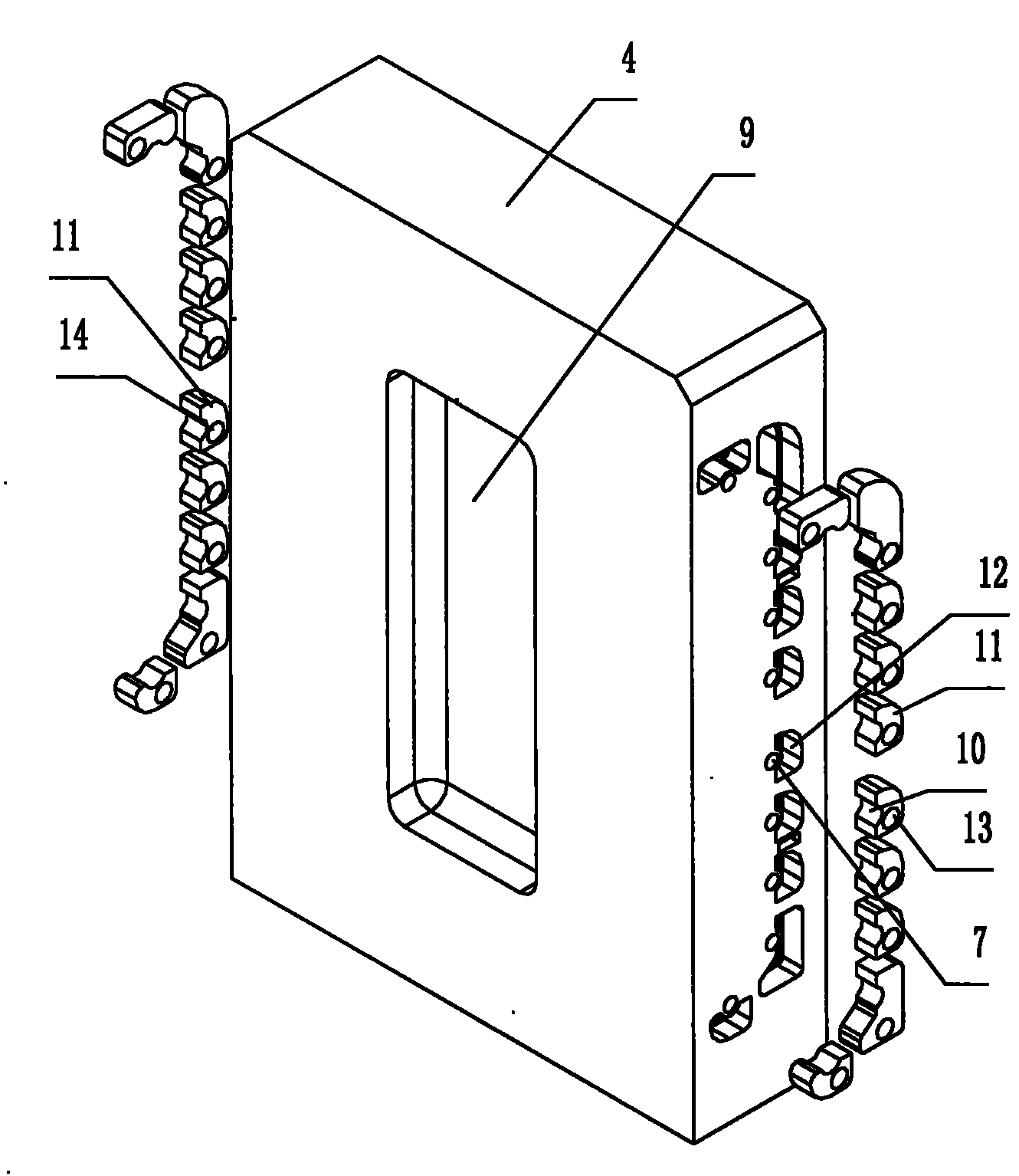
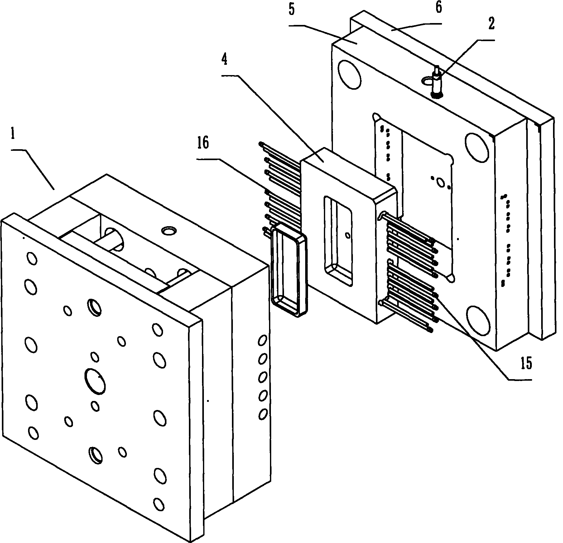
The invention discloses a mould capable of realizing a rapid heat cycle, which comprises a mould core provided with a moulding surface and heating rods with set number. Heating rod accommodating holes are formed at positions close to the moulding surface in the mould core and accommodate the heating rods; cooling insulation holes corresponding to the heating rods are formed at positions close to the heating rods in the mould core provided with the moulding surface, and are positioned on one side of the heating rods far from the moulding surface; the overall outline of the cross section of each cooling insulation hole is a closed curve; and one or more cooling insulation holes enclose corresponding heating rods in three directions. The mould has the advantages that: the moulding surface can be rapidly and uniformly heated and cooled, and can be rapidly heated to the temperature approaching to or equal to the temperature of a fused material, so the moulded products have good quality, weld marks, flow marks, surface bubbles and the like are not generated easily, the products have uniform luster and density and low shrinkage, and injection pressure and product deformation caused by residual stress after the fused material is solidified and moulded are reduced.
Description
A mold capable of rapid cooling and rapid heating technical field The invention relates to a mold with a temperature control device, in particular to a mold capable of rapid cooling and rapid heating on molding machines such as injection die casting. Background technique The injection molding method of plastic or metal refers to injecting molten plastic or metal into the molding cavity of the mold, and obtaining a product consistent with the cavity after cooling and molding. In the injection molding process, heating and cooling devices are required to adjust and control the temperature of the mold to improve product quality. Existing mold temperature control devices generally use electric heating wires to heat water or oil as a liquid heat-conducting medium, and then flow into the mold to heat the mold. Among them, the water heat transfer medium can only be heated to 100°C in principle, and the oil heat transfer medium can only be heated to 200°C in principle. This heati...
Claims
Login to View More Application Information
Patent Timeline
 Patent Type & Authority Applications(China)
IPC IPC(8): B29C33/02B29C33/04B29C45/26B29C45/73B29C45/78B22D17/22B22D17/20B22D17/32
CPCB29C45/73B29C33/04B29C2045/7393
Inventor 杨东佐
Owner 杨东佐
Features
- R&D
- Intellectual Property
- Life Sciences
- Materials
- Tech Scout
- Unparalleled Data Quality
- Higher Quality Content
- 60% Fewer Hallucinations
Learn More Browse by: Latest US Patents, China's latest patents, Technical Efficacy Thesaurus, Application Domain, Technology Topic, Popular Technical Reports.
© 2025 PatSnap. All rights reserved.Legal|Privacy policy|Modern Slavery Act Transparency Statement|Sitemap|About US| Contact US: help@patsnap.com


