
Piezoelectric dynamic plasticizing forming device and injection molding method thereof

A molding device and dynamic technology, applied in the field of plasticizing molding devices, can solve the problems of inability to achieve sub-ultrasonic vibration frequency, driving frequency, adjustment of applied voltage driving waveform, inability to achieve amplitude, etc., to promote orientation and stretching, and avoid shrinkage. Empty, ordered effect

Active Publication Date: 2012-01-11
重庆市仁盛机械有限公司
View PDF6 Cites 15 Cited by
  • Summary
  • Abstract
  • Description
  • Claims
  • Application Information

AI Technical Summary

Problems solved by technology

The above-mentioned vibration frequency is 0-300 Hz, and the amplitude is 0-1.5 mm. It cannot achieve sub-micron amplitude, nor can it reach the sub-ultrasonic vibration frequency of 16 kHz to 20 kHz, and the driving frequency, applied voltage, and driving waveform cannot be adjusted according to different plastics. feature tweaks

Method used


Image

  • Piezoelectric dynamic plasticizing forming device and injection molding method thereof
  • Piezoelectric dynamic plasticizing forming device and injection molding method thereof
  • Piezoelectric dynamic plasticizing forming device and injection molding method thereof

Examples


Embodiment 1)

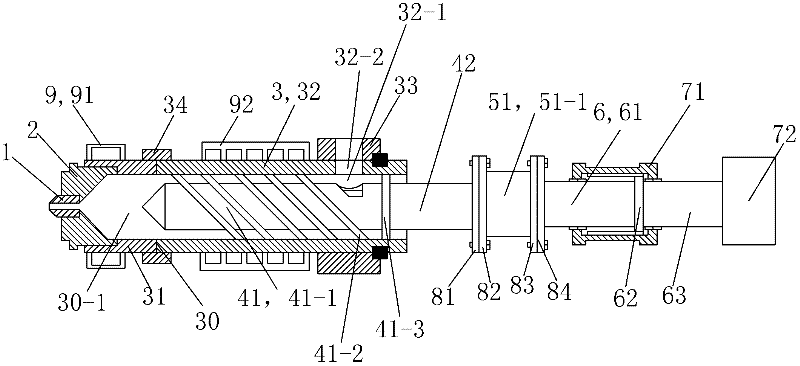
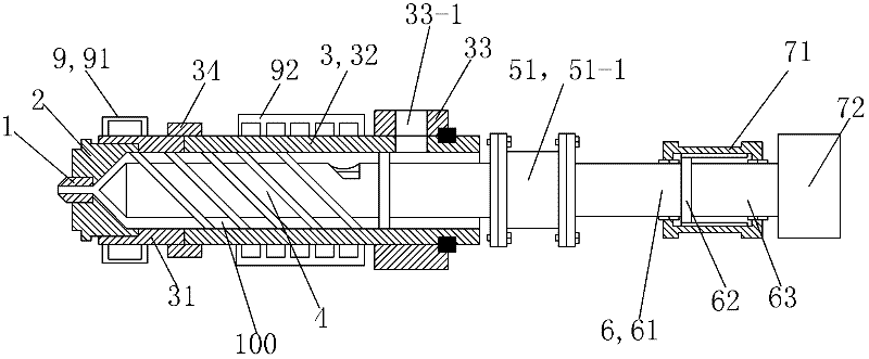
[0046] See figure 1 , The piezoelectric dynamic plasticizing molding device of this embodiment includes a frame, a nozzle 1, a nozzle seat 2, a material tube 3, a compression screw 4, a piezoelectric ceramic actuator 51, a piston rod 6, a hydraulic cylinder 71, and a hydraulic motor 72 and heating jacket9. The nozzle 1, the nozzle seat 2 and the barrel 3 are coaxially arranged and connected in sequence from front to back and from inside to outside. Hydraulic cylinder 71 is fixed on the frame by its cylinder body, and hydraulic cylinder 71 and hydraulic motor 72 are all provided with the interface that links to each other with hydraulic pump when using.

[0047] The rack (not shown) sits and is secured to the ground. The feed pipe 3 is composed of a feed pipe head 31, a feed pipe main body 32, a feeding trough 33 and a connecting sleeve 34; the feed pipe 3 is installed on the frame by its feed pipe main body 32. The material pipe head 31 is a cylindrical steel integral part ...


PUM


Abstract

The invention discloses a piezoelectric dynamic plasticizing forming device and an injection molding method thereof. The forming device is characterized in that: the forming device comprises, sequentially connected from front to back, a nozzle, a nozzle seat, a material tube, a compression screw, a piezoelectric ceramic driving system, a hydraulic cylinder, and a hydraulic motor; the material tube is provided with a heating jacket, and the hydraulic cylinder and the hydraulic motor are connected with a hydraulic pump; the nozzle seat is connected to the front end of the material tube, and the nozzle is connected to the nozzle seat; the compression screw is positioned in the space of the material tube, and the back end of the piston rod, which extrudes the material tube, is connected with the front end of a piezoelectric ceramic; the back end of the piezoelectric ceramic is connected with a piston rod, two ends of the piston rod extrude the hydraulic cylinder, and the back end of the piston rod is fixedly connected with the hydraulic motor. The injection molding method comprises the following steps: a reverse piezoelectric effect of the piezoelectric ceramic is utilized, and a computer controls the piezoelectric ceramic to generate a driving signal, so the piezoelectric ceramic vibrates in an axial direction and the frequency and the amplitude of the vibration are controllable; the compression screw reciprocatingly vibrates in a small amplitude, high frequency, and high acceleration mode; and products with higher intensity than common products are finally obtained by mixing and injection molding.

Description

technical field [0001] The invention relates to a plasticizing molding device, in particular to a device capable of realizing dynamic plasticizing molding processing and an injection molding method thereof. Background technique [0002] In the traditional injection molding process, the melting of plastic is completely completed by external heating and mechanical shearing, and the final die flow is carried out under the action of a stable external force. Due to the poor heat transfer performance of the plastic itself, on a traditional injection machine, in order to completely melt the plastic in the barrel, it often requires a relatively high external temperature to truly transfer heat to the inner plastic. At the same time, because the screw moves back and forth along the axis during the plasticization and injection process, the residence time of the plastic in the barrel is inconsistent, and the heating and shearing processes it bears are also different. To make the plasti...

Claims


Application Information

Patent Timeline
IPC IPC(8): B29C45/03B29C45/50B29C45/20B29C45/17B29C45/18
Inventor 刘天军沈洪雷
Owner 重庆市仁盛机械有限公司
Learn More