Water diversion valve for flushing closestool and closestool

A water separation valve and flushing technology, which is applied in flushing toilets, water supply devices, flushing equipment with water tanks, etc. Effect

Pending Publication Date: 2018-10-19
ZHEJIANG IKAHE SANITARY WARES
View PDF5 Cites 3 Cited by
  • Summary
  • Abstract
  • Description
  • Claims
  • Application Information

AI Technical Summary

Problems solved by technology

[0003] The technical problem to be solved by the present invention is that the structure of the dispersing device used in the existing dual-waterway flushing toilet is complicated and the noise is large

Method used


Image

  • Water diversion valve for flushing closestool and closestool
  • Water diversion valve for flushing closestool and closestool
  • Water diversion valve for flushing closestool and closestool

Examples


Embodiment 1

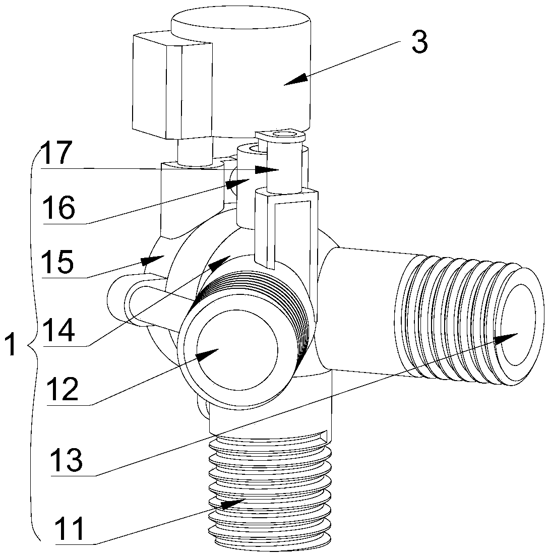
[0027] refer to Figure 1 to Figure 3 , this embodiment discloses a water diversion valve for toilet flushing, including a body 1 , a ball valve 2 and a motor 3 .

[0028] The main body 1 is provided with an accommodation cavity (not marked in the figure), and the main body 1 is provided with a water inlet 11, a side flush port 12 and a siphon port 13; the side flush port 12 and the siphon port 13 are located on the side of the body 1, The water inlet 11 is located at the lower end of the body 1 .

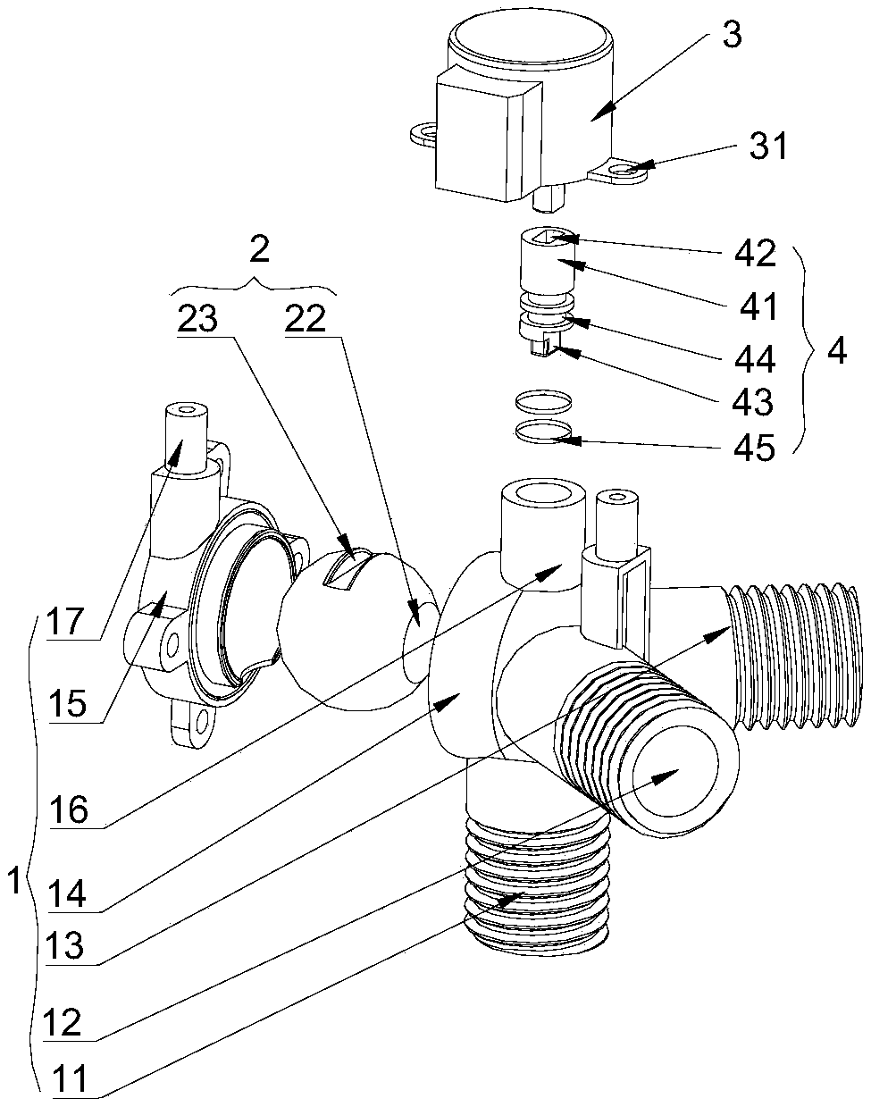
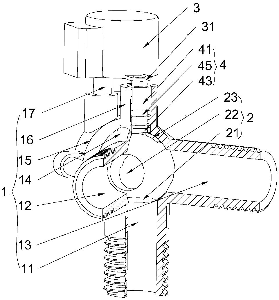
[0029] The ball valve 2 is located in the housing cavity, such as Figure 4 As shown, the ball valve 2 is provided with a water inlet channel 21 and a water outlet channel 22 which communicate with each other, and the ball valve 2 is provided with a second groove 23; the water inlet channel 21 communicates with the water inlet 12; the motor 3 is connected with the ball valve 2 , and drive the ball valve 2 to rotate, so that the water outlet channel 22 can communicate with the sid...

Embodiment 2

[0037] The difference between this embodiment and the first embodiment is that the body 1 includes a valve body 14 and a valve cover 15 . The accommodating cavity is arranged in the valve body 14, and the accommodating cavity has an opening (not shown in the figure), the ball valve 2 is arranged in the accommodating cavity, and the valve cover 15 covers the opening, and the ball valve 2 closed in the containing chamber. The main body 1 is set as a split structure for open mold production.

[0038] Such as figure 2 As shown, in this embodiment, the water inlet 11 is disposed at the lower end of the valve body 14 , and the side flush 12 , siphon port 12 and the opening are all disposed on the side wall of the valve body 14 . When there are two connecting ears 31 and they are arranged symmetrically, preferably, one of the corresponding studs 17 is arranged on the valve body 14 and the other is arranged on the valve cover 15 .

Embodiment 3

[0040] The difference between this embodiment and the second embodiment is that the side flush port 12 and the siphon port 13 are arranged on the side wall of the valve body 14, the opening shown is arranged at the lower end of the valve body 14, and the water inlet 11 is arranged at the valve body 14. Cover 15. Correspondingly, the studs 17 for cooperating with the connecting ears 31 are all arranged on the valve body 14 .


PUM


Abstract

The invention discloses a water diversion valve for flushing a closestool. The water diversion valve comprises a body, a ball valve and a motor, wherein a containing cavity is formed in the body; a water inlet, a side flushing opening and a siphon opening are formed in the body; the ball valve is located in the containing cavity; the ball valve is provide with a water inlet passage and a water outlet passage which are communicated with each other; the water inlet passage is communicated with the water inlet; the motor is connected with the ball valve through a transmission device; along with rotating of the ball valve, the water outlet passage is communicated with the side flushing opening or is communicated with the siphon opening. The invention also provides the closestool using the electric water diversion valve. The water diversion valve provided by the invention has the advantages that the ball valve is driven to rotate through the motor, so that quick switching between the side flushing opening and the siphon opening is realized; the water diversion valve is simple in structure and low in cost, is smooth in waterway switching during a using process, and basically has no noise.

Description

technical field [0001] The invention belongs to the technical field of bathroom devices, and in particular relates to a water diversion valve for toilet flushing and a toilet. Background technique [0002] Toilet flushing systems are generally divided into two types: one is side flush single-way flushing, water flows out from the upper side of the ceramic to wash away the stolen goods; the other is dual-channel flushing, part of the water flows from the upper side of the ceramic The outflow is the side flush, and another part of the water is sprayed from the bottom of the ceramic to form a siphon, thereby using the siphon principle to wash away the stolen goods. The flushing effect of the first method is not good, and wastes water, so the current toilet generally adopts dual waterway flushing. Since there is only one waterway entering the toilet, a water diversion device needs to be provided. Existing water diversion devices are generally integrated into the valve body, wi...

Claims


Application Information

Patent Timeline
Patent Type & Authority Applications(China)
IPC IPC(8): E03D11/02E03D5/00
CPCE03D5/00E03D11/02
Inventor 袁金广刘瑞林峰
Owner ZHEJIANG IKAHE SANITARY WARES
Why Eureka
Try Eureka