Flat gate valve

A flat gate valve and valve stem technology, which is applied to sliding valves, valve devices, engine components, etc., can solve the problems of inaccurate judgment of the operating position of the gate, erosion of the gate, etc. Effect

Pending Publication Date: 2018-10-19
DEYANG DIXINJIA VALVE MFR
View PDF10 Cites 0 Cited by
  • Summary
  • Abstract
  • Description
  • Claims
  • Application Information

AI Technical Summary

Problems solved by technology

[0004] The valve seat of this patent also includes a mounting groove located inside the seat body around its circumference, and a tensioning ring disposed in the mounting groove so that the connection between the valve seat and the channel port has a tendency to tighten. The tensioning ring makes the valve seat and the valve The tightness of the body is strengthened to reduce the occurrence of leakage accidents, but solid particles are easy to corrode the gate, and the operating position of the gate cannot be accurately judged

Method used


Image

  • Flat gate valve
  • Flat gate valve
  • Flat gate valve

Examples


Embodiment 1

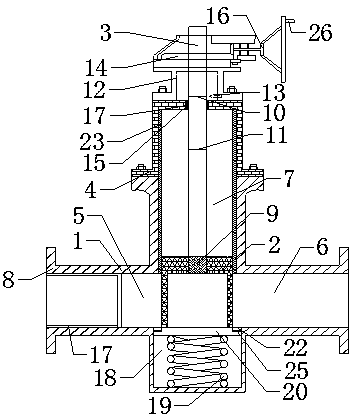
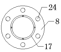
[0028] As a most basic embodiment of the present invention, this embodiment discloses a flat gate valve, such as figure 1 As shown, it includes a valve body 1, a gate plate 2, a valve stem 3 and a bonnet 4. The valve body 1 is provided with an inflow channel 5, an outflow channel 6 and an upper channel 7. The end of the inflow channel 5 and the outflow channel 6 ends are provided with a flange 8, the upper end of the valve body 1 is connected to the valve cover 4, the valve stem 3 penetrates the valve cover 4 and enters the interior of the valve body 1, and the valve stem 3 passes through the connecting block 9 and the gate plate 2 connected, the valve stem 3 is provided with an upper limit indicating line 10 and a lower limit indicating line 11, the valve cover 4 is connected with a bracket 12, and the bracket 12 is provided with a pointer 13, the pointer 13, the upper limit indicating line 10 Work together with the lower limit indicator line 11 to indicate the position of th...

Embodiment 2

[0031] As a preferred embodiment of the present invention, this embodiment discloses a flat gate valve, such as figure 1As shown, it includes a valve body 1, a gate plate 2, a valve stem 3 and a bonnet 4. The valve body 1 is provided with an inflow channel 5, an outflow channel 6 and an upper channel 7. The end of the inflow channel 5 and the outflow channel 6 ends are provided with a flange 8, the upper end of the valve body 1 is connected to the valve cover 4, the valve stem 3 penetrates the valve cover 4 and enters the interior of the valve body 1, and the valve stem 3 passes through the connecting block 9 and the gate plate 2 connected, the valve stem 3 is provided with an upper limit indicating line 10 and a lower limit indicating line 11, the valve cover 4 is connected with a bracket 12, and the bracket 12 is provided with a pointer 13, the pointer 13, the upper limit indicating line 10 Work together with the lower limit indicator line 11 to indicate the position of the ...


PUM


Abstract

The invention discloses a flat gate valve, and belongs to the technical field of valves. The flat gate valve comprises a valve body, a valve plate, a valve rod and a valve cover; an inflow channel, anoutflow channel and an upper channel are formed in the valve body; flange plates are arranged at the end of the inflow channel and the end of the outflow channel correspondingly, the upper end of thevalve body is connected with the valve cover, the valve rod penetrates through the valve cover to enter the valve body, and the valve rod is connected with a gate plate through a connecting block; the valve rod is provided with an upper limit indicating line and a lower limit indicating line, the valve cover is connected with a bracket, and the bracket is provided with a pointer; a rotating discis arranged on the bracket and is in threaded connection with the valve rod, a mechanical sealing ring is arranged at the matched position of the valve rod and the valve cover, and the rotating disc is engaged with a hand wheel; a filter net is arranged in the inflow channel, a groove is formed in the bottom of the valve body, a spring is arranged in the groove, a baffle is arranged on the spring,stopping grooves are formed in the two ends of the upper portion of the baffle correspondingly, stopping blocks are symmetrically arranged on the left side and the right side at an opening of the groove, and the stopping blocks are welded to the opening of the groove; and the length and the width of the stopping blocks are equal to the length and the width of the stopping grooves.

Description

technical field [0001] The invention belongs to the technical field of valves, and in particular relates to a flat gate valve. Background technique [0002] The gate valve is generally used to open or close the medium flow of the pipeline. The opening and closing part is a gate, and the movement direction of the gate is perpendicular to the direction of the fluid. The gate valve can only be used for full opening and full closing, not for regulation and throttling. Among them, the slab gate valve is a sliding valve whose closing parts are parallel gates. The closing part can be a single ram or a double ram with a stretching mechanism in between. The advantages of the flat gate valve are simple shape, short structure length, small resistance, unrestricted medium flow direction, and no disturbance; the disadvantage is that it is easy to cause erosion and scratches between the sealing surfaces, and it is difficult to maintain, especially when the bottom of the valve seat accum...

Claims


Application Information

Patent Timeline
Patent Type & Authority Applications(China)
IPC IPC(8): F16K3/02F16K37/00
CPCF16K3/0209F16K37/0016
Inventor 黄斌李红帅袁泓杉
Owner DEYANG DIXINJIA VALVE MFR
Why Eureka
Try Eureka