Fixture and smart ophthalmoscope using it
A technology of fixing devices and fixing parts, applied in the field of smart ophthalmoscopes, can solve the problems of patients losing treatment opportunities, causing blindness, and affecting the quality of life.
- Summary
- Abstract
- Description
- Claims
- Application Information
AI Technical Summary
Problems solved by technology
Method used
Image
Examples
Embodiment 1
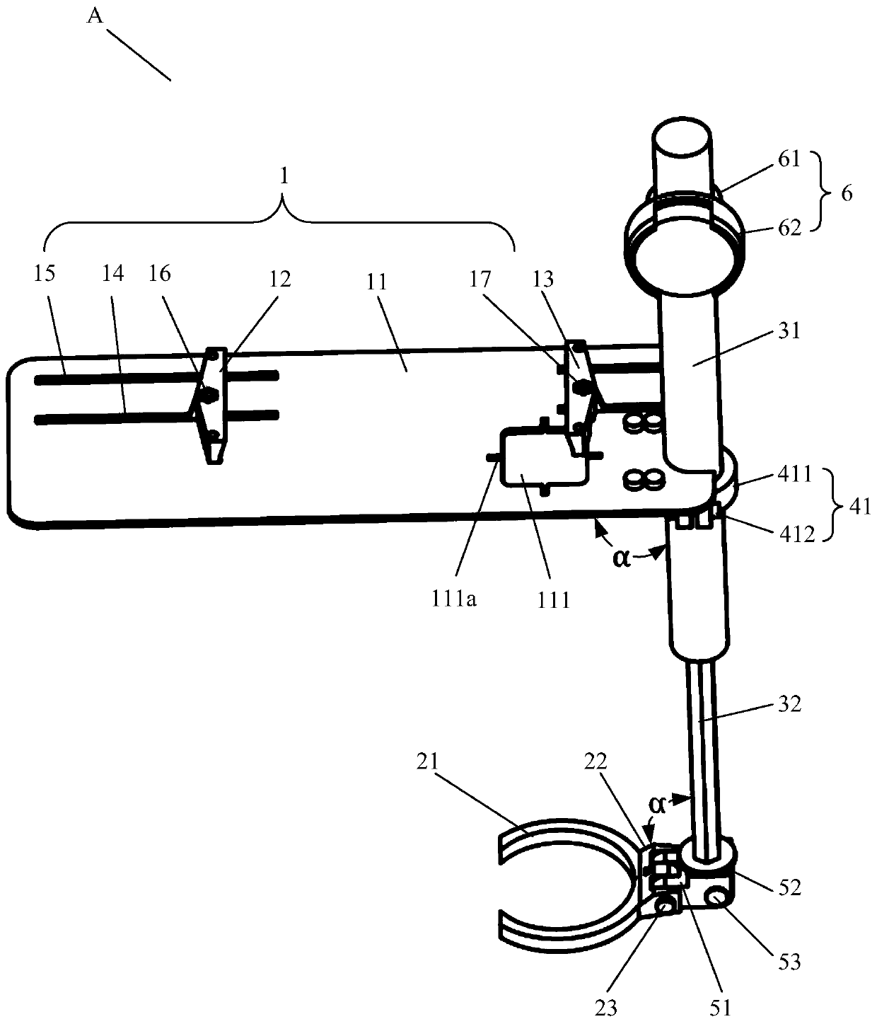
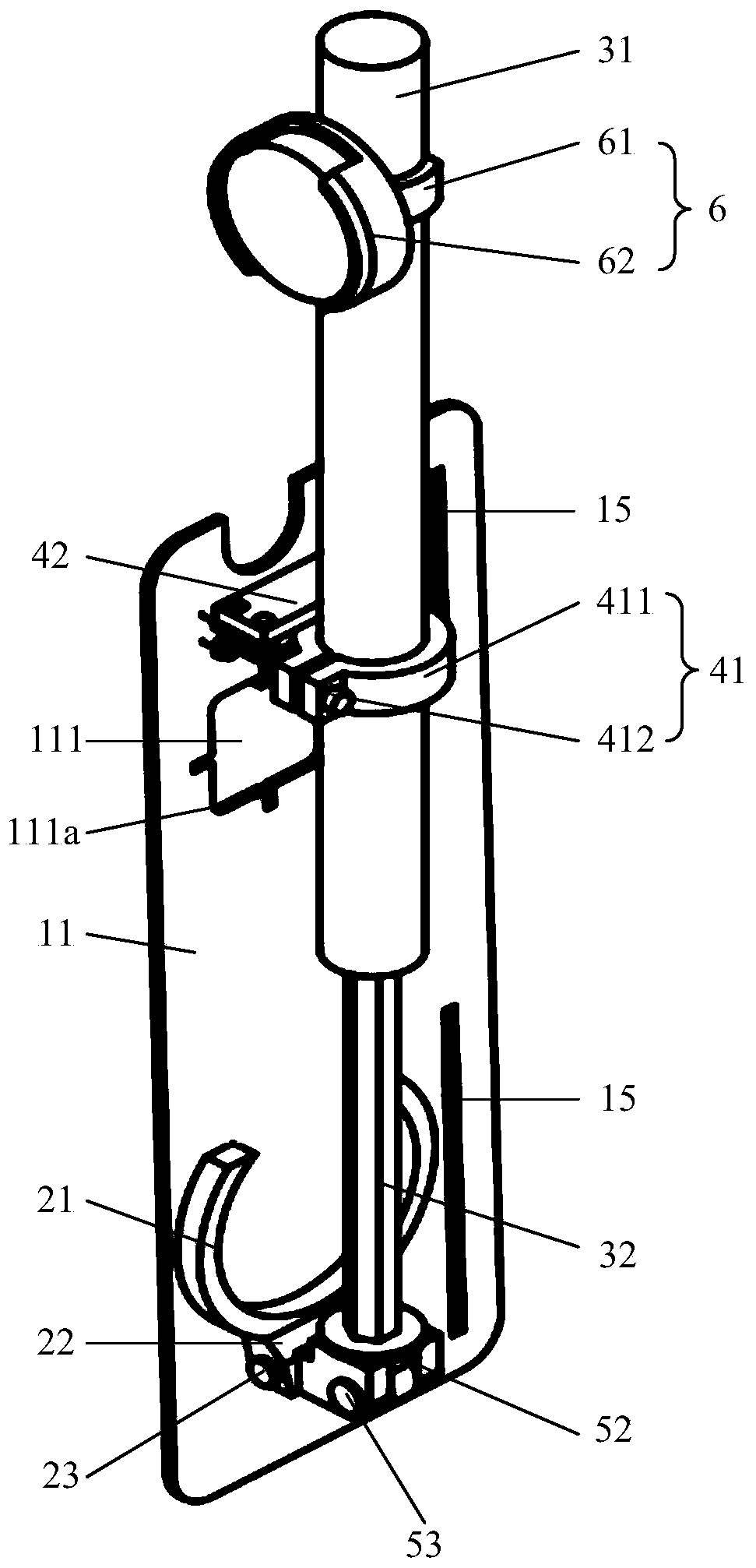
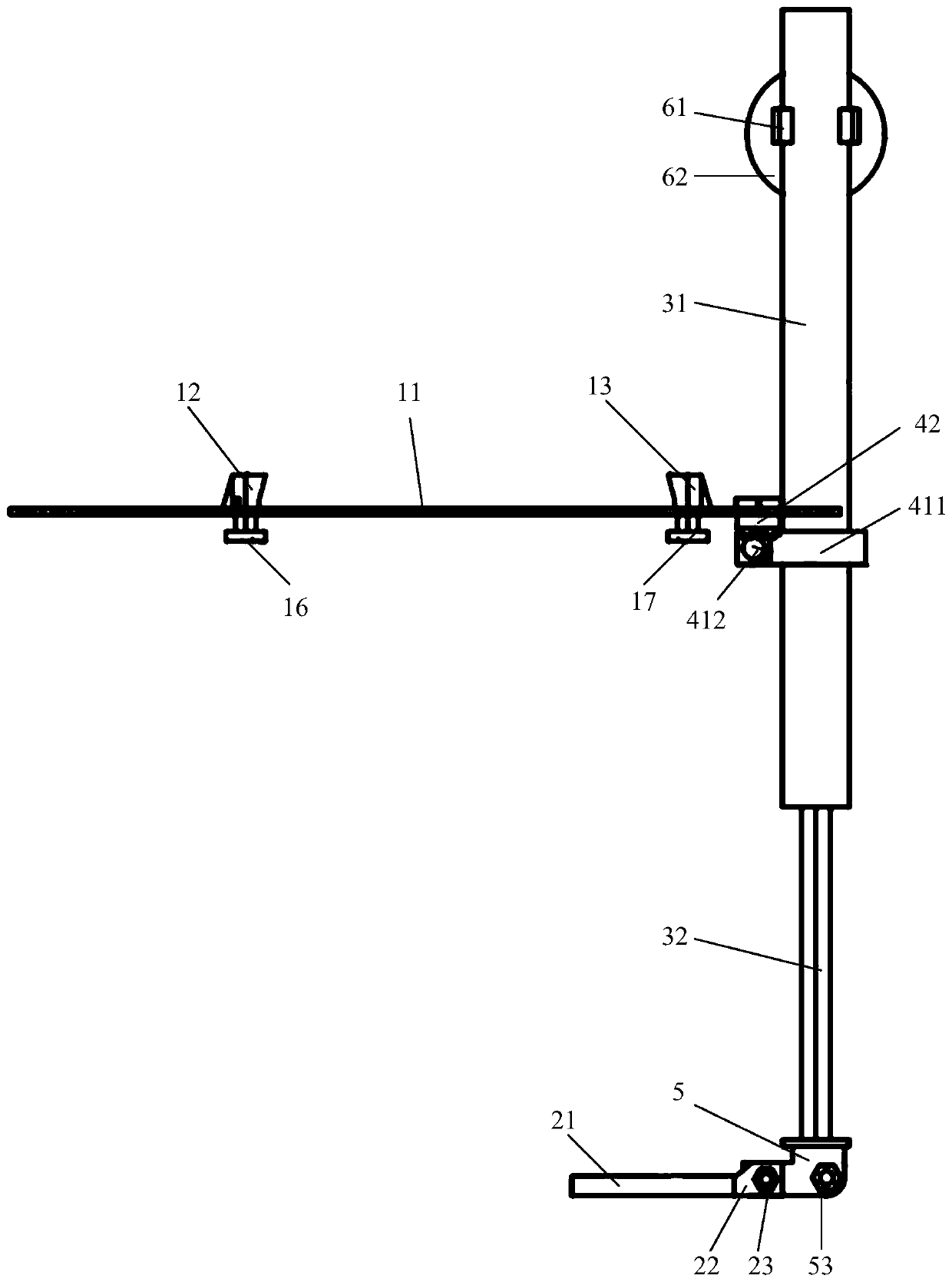
[0099] Figure 1-Figure 3 This is a schematic diagram of a fixing device according to an embodiment of this application. Such as Figure 1-Figure 3 As shown, the fixing device A includes a first fixing part 1, a second fixing part 2, a main body 3, a first connecting part 4, a second connecting part 5 and a third connecting part 6. The first fixing member 1 is rotatably connected to the main body 3 through the first connecting member 4. The second fixing member 2 is rotatably connected with the main body 3 through the second connecting member 5. Wherein, the relative distance between the first fixing part 1 and the second fixing part 2 is adjustable. The first fixing part 1 is used to fix the mobile terminal B (not shown in the figure), and the second fixing part 2 is used to fix the optical lens C (not shown in the figure), thereby forming a simple portable smart ophthalmoscope. The first fixing part 1 and the second fixing part 2 are configured in a folded state and an unfo...
Embodiment 2
[0120] Picture 11 with Picture 12 This is a schematic structural diagram of a fixing device according to an embodiment of the present application. Such as Figure 11-12 As shown, the structure of the fixing device of the present application is basically the same as the structure of the fixing device of the first embodiment, except that the structure of the first fixing component 1 is different from the structure of the first fixing component 1 of the first embodiment. details as follows:
[0121] The first fixed part 1 includes a support plate 11, a first sliding part 12, a second sliding part 13, a first set of fixed blocks 18, a second set of fixed blocks 19, a first guide rail 110 and a second guide rail 120. Both the first group of fixed blocks 18 and the second group of fixed blocks 19 include two mutually parallel fixed blocks, which are respectively fixedly connected to the supporting plate 11 and arranged at the bottom of the supporting plate 11. Each fixing block is ...
Embodiment 3
[0126] This embodiment provides a smart ophthalmoscope, including a fixing device A, a mobile terminal B (not shown in the figure) and an optical lens C (not shown in the figure). The structure of the fixing device A is the same as the structure described in the first and second embodiments. The mobile terminal B includes a mobile phone, a camera, a tablet computer, etc. The mobile terminal B includes a camera and a light-emitting unit, and is clamped and fixed on the support plate 11 by a first sliding part 12 and a second sliding part 13. The camera and light-emitting unit of the mobile terminal B are exposed through the observation window 111 for shooting and obtaining eye images. The optical lens C is fixed on the clamping portion 21 of the second fixing member 2. In this embodiment, the distance between the mobile terminal B and the optical lens C is adjusted by the expansion and contraction of the main body 3. At the same time, the mobile terminal B and the optical len...
PUM
 Abstract
Description
Claims
Application Information
 - R&D
- Intellectual Property
- Life Sciences
- Materials
- Tech Scout
- Unparalleled Data Quality
- Higher Quality Content
- 60% Fewer Hallucinations
Browse by: Latest US Patents, China's latest patents, Technical Efficacy Thesaurus, Application Domain, Technology Topic, Popular Technical Reports.
© 2025 PatSnap. All rights reserved.Legal|Privacy policy|Modern Slavery Act Transparency Statement|Sitemap|About US| Contact US: help@patsnap.com


