

Temporary storage mechanism for clothes hanger on clothing hanging production line
A temporary storage mechanism and production line technology, applied in the field of machinery, can solve problems such as increasing the difficulty of operations, and achieve the effects of high practical value, convenient operation, and high connection stability
- Summary
- Abstract
- Description
- Claims
- Application Information
AI Technical Summary
Problems solved by technology
Method used
Image

Examples
Embodiment Construction
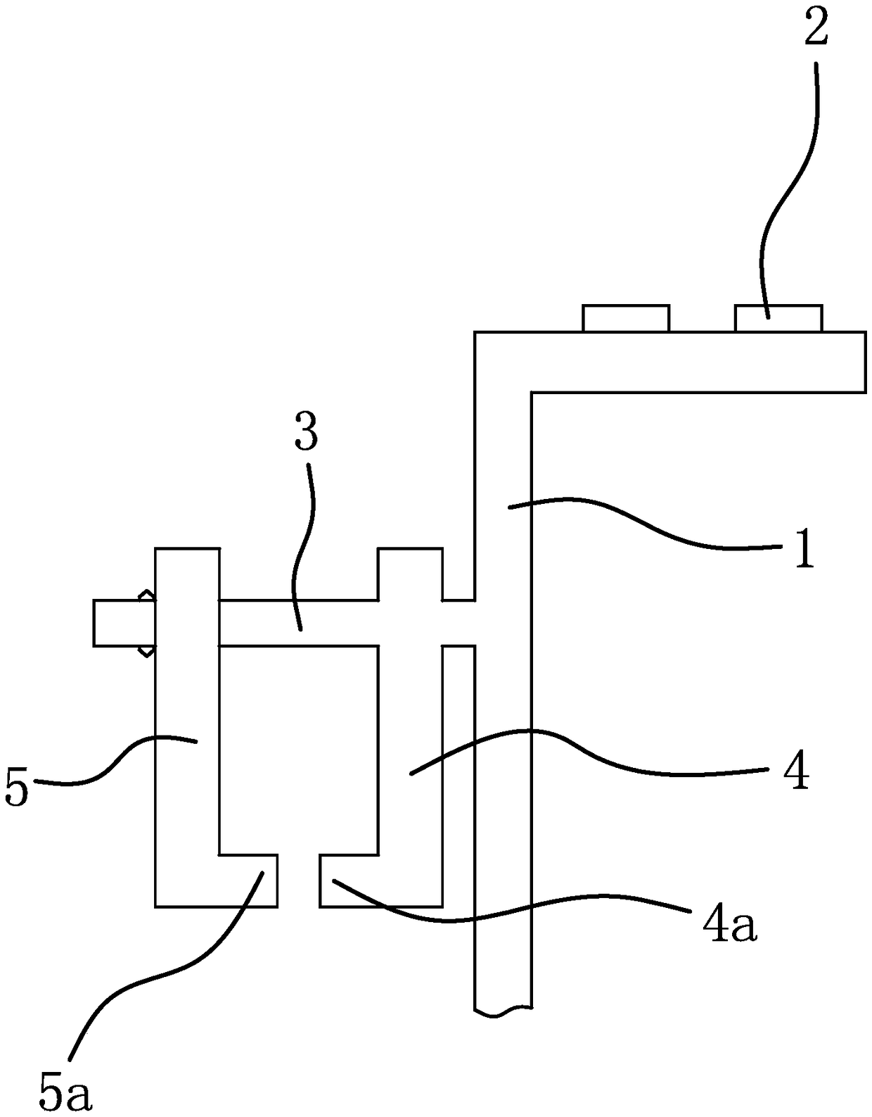
[0031] Such as figure 1 and figure 2 As shown, the garment hanging production line includes a bracket 1 and a guide rail 2 , and the guide rail 2 is fixedly connected to one side of the bracket 1 .
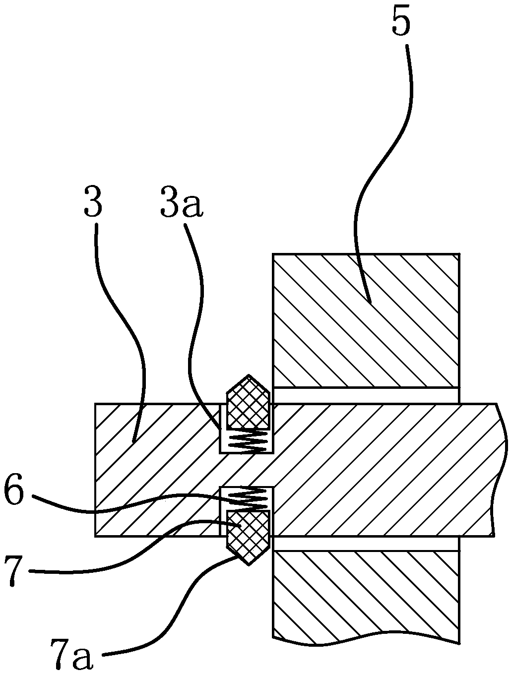
[0032] The temporary storage mechanism of the clothes hanger on the garment hanging production line is located on the other side of the support 1, and includes a positioning beam 3, a fixed plate 4 and a movable plate 5. Plate 4 is fixedly connected with positioning beam 3, above-mentioned movable plate 5 is movably connected on positioning beam 3 and has a locking structure capable of locking movable plate 5 between movable plate 5 and positioning beam 3, and said fixed plate 4 has The positioning part 1 is used for positioning one side of the clothes hanger, and the movable plate 5 has a positioning part 2 for positioning the other side of the clothes hanger.
[0033] The first positioning part is a protruding edge 4a at the lower end of the fixing plate 4 .
[0034] The sec...
PUM
 Abstract
Description
Claims
Application Information