
Novel simple rail clamping device

A rail clamp, a simple technology, applied in the direction of walking mechanism, load hanging components, transportation and packaging, etc., can solve the problems of increasing installation difficulty for installers, complex structure of rail clamp, no protective device, etc., to avoid sliding rails Or get off track, reduce production costs, and have high practical effects

Pending Publication Date: 2018-10-23
HENAN SINOKO CRANES
View PDF8 Cites 1 Cited by
  • Summary
  • Abstract
  • Description
  • Claims
  • Application Information

AI Technical Summary

Problems solved by technology

The structure of the existing rail clamp is relatively complicated, which is not easy to install, which increases the difficulty of installation for the installers
And there is no protective device, there are certain risks in the process of use

Method used


Image

  • Novel simple rail clamping device
  • Novel simple rail clamping device
  • Novel simple rail clamping device

Examples


Embodiment Construction

[0015] In order to understand the above-mentioned purpose, features and advantages of the present invention more clearly, the present invention will be further described in detail below in conjunction with the accompanying drawings and specific embodiments.

[0016] In the following description, many specific details are set forth in order to fully understand the present invention. However, the present invention can also be implemented in other ways different from those described here. Therefore, the protection scope of the present invention is not limited by the content disclosed below. limits.

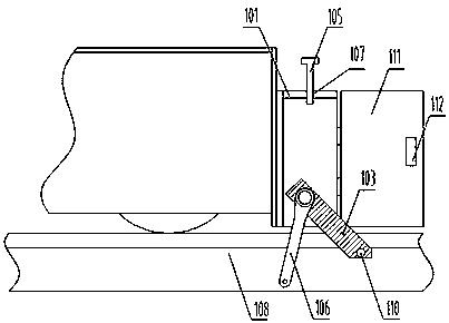
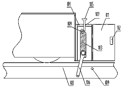
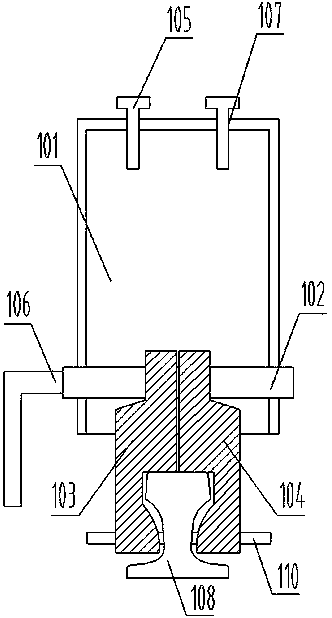
[0017] The following combination figure 1 , figure 2 and image 3 The technical scheme of the present invention will be further described.

[0018] Such as figure 1 , figure 2 and image 3 As shown, a new type of simple rail clamp includes: a cabinet body 101, a two-way screw rod 102, a first splint 103, a second splint 104, a long bolt 105 and a handle 106, and the lower par...


PUM


Abstract

The invention relates to a novel simple rail clamping device. The novel simple rail clamping device comprises a cabinet body, a double-way screw rod, a first clamping plate, a second clamping plate, along bolt and a handle. The double-way screw rod horizontally arranged is arranged on the lower part in the cabinet body. The first clamping plate and the second clamping plate are symmetrically arranged on the double-way screw rod. A thread is arranged on the double-way screw rod. When the double-way screw rod rotates, the first clamping plate and the second clamping plate move in the opposite directions. A threaded hole is formed in the top of the cabinet body. The long bolt is movably arranged in the threaded hole. The handle is arranged on the outer side of the cabinet body. The handle isconnected to the double-way screw rod. The novel simple rail clamping device is simple in overall structure, and the manufacturing cost is lowered; during installation, only a box body needs to be correspondingly mounted on a main machine, and the difficulty of installation is reduced; and moreover, the novel simple rail clamping device has the dual-protection function and high practicability andis worthy of application and popularization.

Description

technical field [0001] The invention relates to a rail clamp, in particular to a novel and simple rail clamp. Background technique [0002] The rail clamp is a safety device that prevents the track-type running machinery from moving freely along the track direction. It is suitable for various bridge-type, gantry cranes and other track-type lifting and handling equipment to resist wind and resist other external impacts. When the main engine is closed and out of service, the rail clamp clamps the rail and drags the main engine to ensure that the main engine will not be blown away by the wind. When the host is in use, the clamp legs are opened by electro-hydraulic or manually to ensure that the host can walk freely on the track. The structure of the existing rail clamp is relatively complicated, and it is not easy to install, which increases the installation difficulty of the installers. Moreover, there is no protective device, and there are certain risks during use. Therefo...

Claims


Application Information

Patent Timeline
Patent Type & Authority Applications(China)
IPC IPC(8): B66C9/18B66C15/00
CPCB66C9/18B66C15/00
Inventor 宋向朋郭丽娟周小飞马玲徐之福
Owner HENAN SINOKO CRANES
Learn More