Withdrawable switchgear

A switchgear, switch unit technology, applied in switchgear, pull-out switchgear, switchgear guards/protectors, etc., can solve the problems of increasing manufacturing and installation time and cost, etc.

Active Publication Date: 2020-09-08
ABB (SCHWEIZ) AG
View PDF5 Cites 0 Cited by
  • Summary
  • Abstract
  • Description
  • Claims
  • Application Information

AI Technical Summary

Problems solved by technology

[0016] Of course, this requires a further increas

Method used


Image

  • Withdrawable switchgear
  • Withdrawable switchgear
  • Withdrawable switchgear

Examples


Embodiment Construction

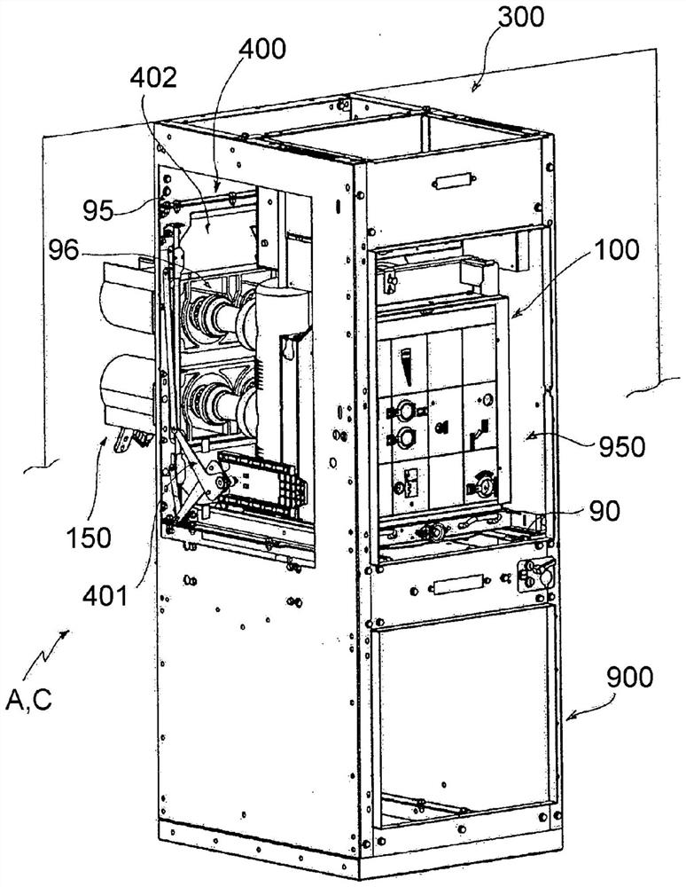
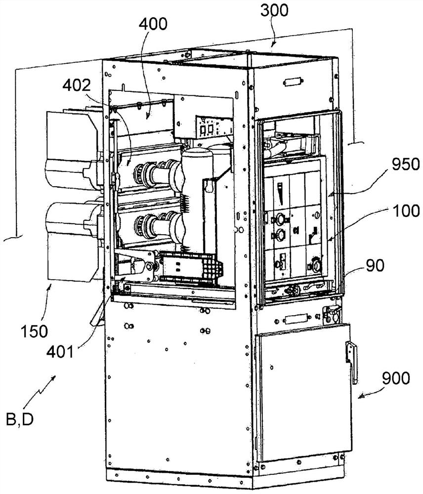
[0057] Referring to the cited figures, one aspect of the invention relates to a switchgear 100 .

[0058] The switchgear 100 is suitable for installation in an electrical switchgear panel 300 .

[0059] Advantageously, the switchgear panel 300 comprises a cabinet 900 which may be of a known type.

[0060] Preferably, the walls of cabinet 900 define one or more compartments for housing various electrical or electronic equipment.

[0061] Preferably, the cabinet 900 includes a compartment 950 for housing the switchgear 100 .

[0062] The cabinet 900 is configured to allow the switchgear 100 to be connected to the electrical line 150 .

[0063] Preferably, the wall 95 of the cabinet 900 partially defining the compartment 950 is provided with one or more access apertures 96 to allow the electrical connection of the switchgear 100 to the electrical circuit 150 .

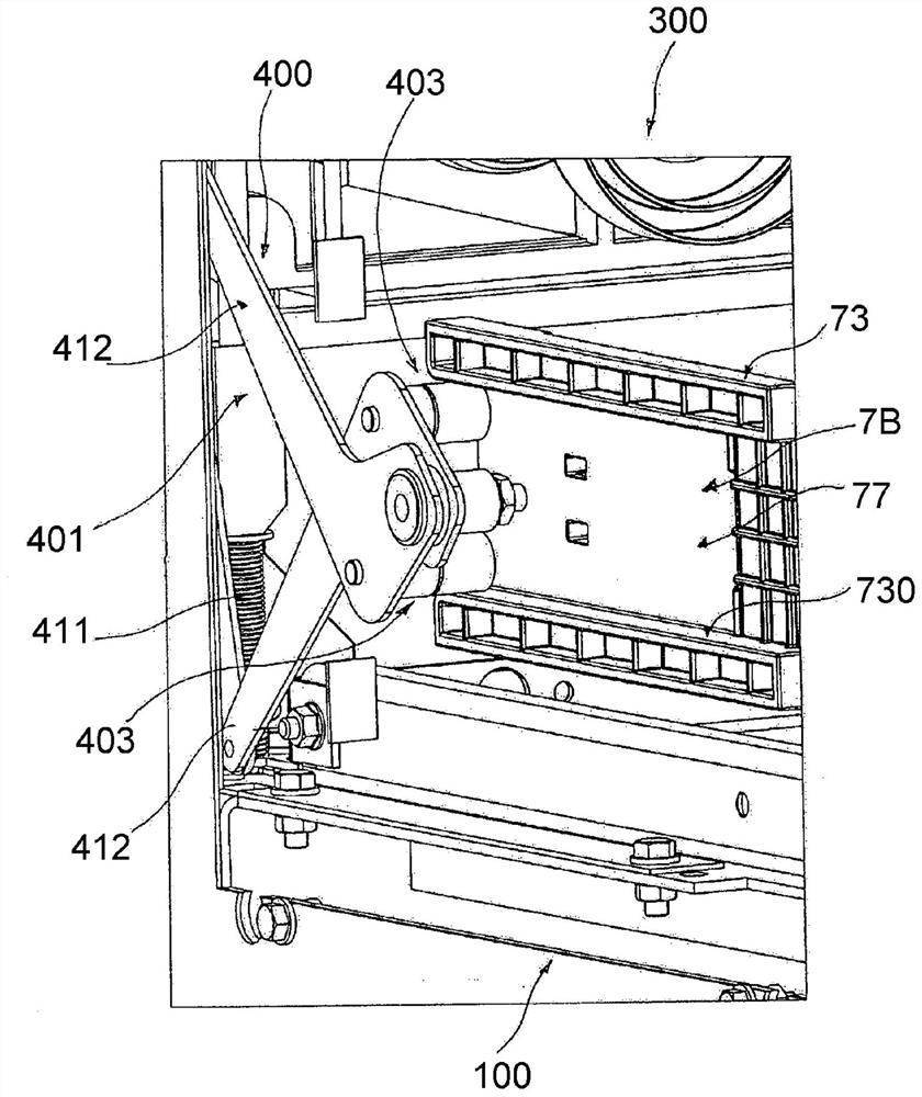
[0064] The switching device 100 comprises a switching unit 2 comprising one or more electrodes 21A, 21B, 21C.

[0065...


PUM


Abstract

A switching device (100) comprising: - a switching unit (2) comprising one or more electric poles (21A, 21B, 21C) having an insulating casing (22), said switching device being reversibly movable between an insertion position (A), at which said switching unit is electrically connected with an electric line (150), and a withdrawal position (B), at which said switching unit is electrically disconnected from said electric line (150); - one or more actuating elements (7A, 7B) operatively coupleable with an actuating mechanism (401) of a shutter device (400) to operate one or more shutters (402) of said shutter device during the movement of said switching device, said actuating elements being fixed to said switching unit. At least one of said actuating elements comprises first mechanical connection means (71) for mechanical connection with the insulating casing of at least one of said electric poles; The insulating casing of at least one of said electric poles comprises second mechanical connection means (220) for mechanical connection with at least one of said actuating elements.

Description

technical field [0001] The present invention relates to the field of switchgear for low or medium voltage applications, such as circuit breakers, contactors, disconnectors and the like. Background technique [0002] For the purposes of this application, the term "low voltage" (LV) relates to operating voltages below 1 kVAC and 1.5 kVDC, while the term "medium voltage" (MV) relates to operating voltages above 1 kVAC and 1.5 kVDC up to a few tens of kV such as up to 72 kVAC and 100 kVDC operating voltage. [0003] Switching devices are widely used in LV or MV applications. [0004] Switchgear for LV or MV applications can be fixed or withdrawable. [0005] Switchgear of the withdrawable type generally includes a switch unit mounted on a rail movable relative to a support base of an electrical switchgear panel in which the switchgear is mounted. [0006] Thanks to the movable trolley, the switching device is movable between an inserted position in which the switching unit is...

Claims


Application Information

Patent Timeline
IPC IPC(8): H02B11/24
CPCH02B11/24H02B11/133H02B11/167
Inventor G·加斯帕里尼G·科尔蒂诺维斯G·莫里科尼
Owner ABB (SCHWEIZ) AG
Why Eureka
Try Eureka