Ceramic disc valve

A ceramic disc and ceramic valve technology, applied in the field of ceramic valves, can solve the problems of wear and corrosion of the ceramic disc valve, stability of lamps, affecting the service life of the ceramic disc valve, poor stability of the ceramic disc valve, etc., to achieve convenient adjustment and increase stable installation. The effect of improving the stability of use

Pending Publication Date: 2018-10-26
HENAN SHENGYU IND
View PDF0 Cites 0 Cited by
  • Summary
  • Abstract
  • Description
  • Claims
  • Application Information

AI Technical Summary

Problems solved by technology

[0003] In the prior art, the existing ceramic disc valves have poor sealing performance when used. At the same time, the valve is in the gas pipeline. Frequent switching operations lead to wear and corrosion of the ceramic disc valve, and the lamp is stable, which affects the service life of the ceramic disc valve. At the same time The stability of the ceramic disc valve is not good when used, so now there is an urgent need for a ceramic disc valve to solve the above problems

Method used


Image

  • Ceramic disc valve
  • Ceramic disc valve
  • Ceramic disc valve

Examples


Embodiment Construction

[0019] In order to make the technical means, creative features, goals and effects achieved by the present invention easy to understand, the present invention will be further described below in conjunction with specific embodiments.

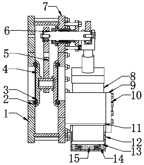
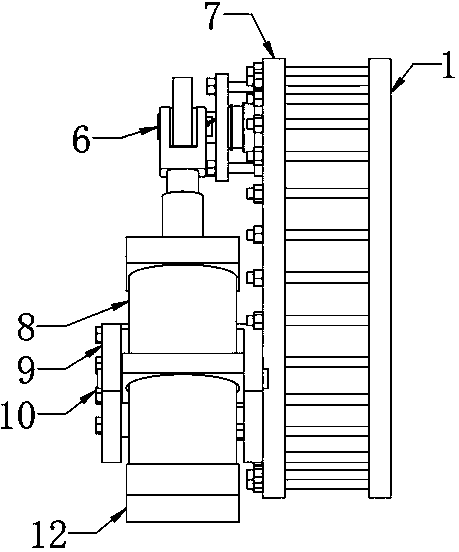
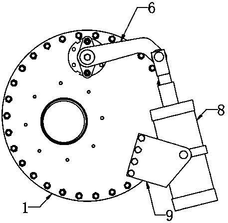
[0020] see Figure 1-Figure 3 , the present invention provides a technical solution: a ceramic disc valve, including a valve body 1, a ceramic valve seat 2, a driving device 7 and an oil cylinder 8, a ceramic valve seat 2 is installed inside the valve body 1, and a ceramic valve seat 2 is installed inside The sealing ring 3, the ceramic valve plate 4 is installed on the right side of the valve body 1, the swing rod 5 is installed on the right side of the ceramic valve plate 4, the valve stem 6 is installed on the upper side of the swing rod 5, and the driving device 7 is installed on the upper side of the valve stem 6, An oil cylinder 8 is installed on the right side of the driving device 7, a protective sheet 9 is installed on the right side of t...


PUM


Abstract

The invention provides a ceramic disc valve. The ceramic disc valve comprises a valve body, a ceramic valve seat, a sealing ring, a ceramic valve plate, a swing rod, a valve rod, a driving device, a locking screw, a spring and muffler cotton; the ceramic valve seat is mounted in the valve body, the sealing ring is mounted in the ceramic valve seat, the ceramic valve plate is mounted on the right side of the valve body, and the swing rod is mounted on the right side of the ceramic valve plate; and the valve rod is mounted on the upper side of the swinging rod, and the driving device is mountedon the upper side of the valve rod. By means of the ceramic disc valve, the problem of poor sealing performance and wear resistance of a ceramic disc valve during using is solved, the locking screw ismounted on the right end surface of a guarding sheet, the spring is mounted on the lower end surface of a moving plate, and the muffler cotton is filled in the lower side of the interior of a base, the problem that a ceramic disc valve is not stable during using is solved, and the ceramic disc valve is reasonable in structure, high in sealing performance, high in stability and fast and convenientto adjust.

Description

technical field [0001] The invention is a ceramic disc valve, which belongs to the technical field of ceramic valves. Background technique [0002] The valve is a control component in the pipeline fluid conveying system, which is used to change the passage section and the flow direction of the medium, and has the functions of diversion, cut-off, throttling, check, diversion or overflow and pressure relief. Valves used for fluid control range from the simplest shut-off valve to various valves used in extremely complex automatic control systems. For valves used in industrial pipelines, the driving device of the ceramic disc valve realizes the switching action of the valve by rotating the valve disc at a certain angle through the valve stem and the driving rocker arm. [0003] In the prior art, the existing ceramic disc valves have poor sealing performance when used. At the same time, the valve is in the gas pipeline. Frequent switching operations lead to wear and corrosion of...

Claims


Application Information

Patent Timeline
Patent Type & Authority Applications(China)
IPC IPC(8): F16K3/06F16K31/16F16K47/02
CPCF16K3/06F16K31/16F16K47/02
Inventor 郑秀娟高青乾司宝成
Owner HENAN SHENGYU IND
Why Eureka
Try Eureka