Cabin air pipe steam trap

A technology for pipe traps and cabins, applied in steam traps, mechanical equipment, etc., can solve the problems of not being able to fill with liquid, and unable to process vent pipes at the top of the cabin.

Inactive Publication Date: 2018-10-26
GUANGXIN SHIPBUILDING & HEAVY IND
View PDF5 Cites 2 Cited by
  • Summary
  • Abstract
  • Description
  • Claims
  • Application Information

AI Technical Summary

Problems solved by technology

[0005] The object of the present invention is a cabin air pipe steam trap, which has a simple structure and can solve the problem that the top of the traditional cabin cannot be processed with a vent pipe and cannot be filled with liquid

Method used


Image

  • Cabin air pipe steam trap
  • Cabin air pipe steam trap

Examples


Embodiment 1

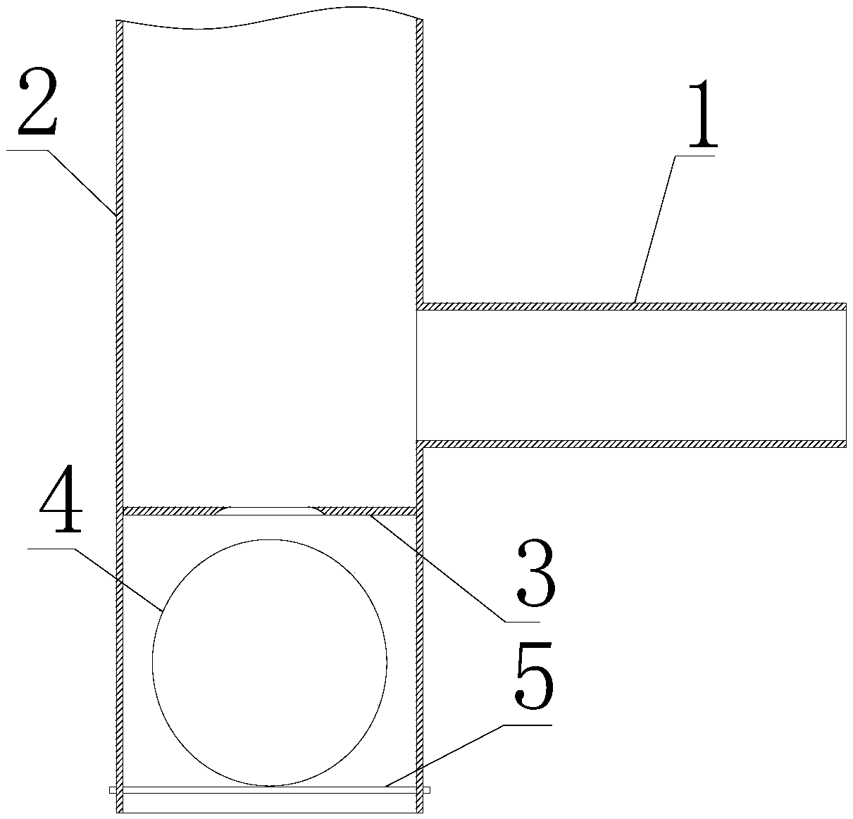
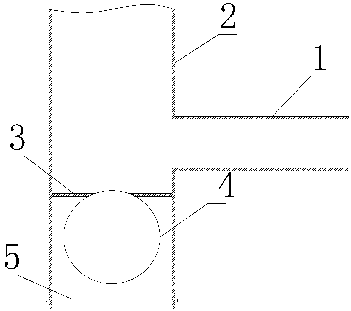
[0017] see Figure 1-2 , a cabin air pipe steam trap, including a vent pipe 1 passing through the side wall of the cabin, and a main pipe 2, the vent pipe 1 is connected to the side wall of the main pipe 2, and the vent pipe 1 is provided with a A valve assembly that opens when the liquid level is lower than the bottom of the main pipe 2 and closes when the liquid level is higher than the bottom of the main pipe 2; the position of the valve assembly is lower than the position where the vent pipe 1 is connected to the main pipe 2, and the The top of the main pipe 2 extends to the top of the cabin.

[0018] During use, the vent pipe 1 is installed on the side wall of the cabin, and the top of the main pipe 2 is extended to the top wall of the cabin. When the liquid in the cabin reaches the bottom of the main pipe 2, if the liquid continues to rise, the valve assembly is closed, and the gas flows from the main pipe. The top of 2 enters the vent pipe 1, and when the liquid rises ...


PUM


Abstract

The invention belongs to the field of pipeline through cabin accessories, and discloses a cabin air pipe steam trap. The cabin air pipe steam trap comprises a vent pipe penetrating through the side wall of a cabin, and further comprises a main pipe; the vent pipe is connected to the side wall of the main pipe; the vent pipe is internally provided with a valve assembly used for being opened when the liquid level is lower than the bottommost of the main pipe and being closed when the liquid level is higher than the bottommost of the main pipe; the position of the valve assembly is lower than theposition where the vent pipe and the main pipe are connected; and the top of the main pipe extends to the top of the cabin. The cabin air pipe steam trap is simple in structure and can solve the problems that a vent pipe cannot be machined on the top of a traditional cabin and the cabin cannot be filled with liquid.

Description

technical field [0001] The invention belongs to the field of pipeline access accessories, and in particular relates to a cabin air pipe steam trap. Background technique [0002] With the deepening of human exploration of the ocean, the requirements for ship performance continue to increase. It is often encountered that ventilation devices cannot be directly installed on the top of the cabin due to the diversity of cabin functional design, complex structure, space limitation, and pipeline layout. How to lead out the ventilation duct from the side and ensure the reasonable position of the air outlet in the cabin, ensure the ventilation of the cabin, facilitate the filling of liquid cargo, and make full use of the volume of the cabin has become an urgent problem to be solved. [0003] Existing technical solutions: At present, there is an existing solution to the arrangement of the ventilation pipes on the side of the cabin. By leading the ventilation pipes on the side of the c...

Claims


Application Information

Patent Timeline
Patent Type & Authority Applications(China)
IPC IPC(8): F16T1/26
CPCF16T1/26
Inventor 谢雨张晨刘宝晶易永光蒋芳叶邹琦
Owner GUANGXIN SHIPBUILDING & HEAVY IND
Why Eureka
Try Eureka