A multi-channel laser transmitter optical component

A technology of laser emitters and optical components, applied in the direction of optical components, optics, instruments, etc., can solve the problem of high price, achieve the effect of cost reduction and meet the requirements of optical power

Active Publication Date: 2020-07-24
DALIAN CANGLONG OPTOELECTRONICS TECH
View PDF6 Cites 0 Cited by
  • Summary
  • Abstract
  • Description
  • Claims
  • Application Information

AI Technical Summary

Problems solved by technology

[0007] The diaphragms used in the technology in the existing literature are complex enough and related to parameters such as polarization state or wavelength, so they are expensive

Method used


Image

  • A multi-channel laser transmitter optical component
  • A multi-channel laser transmitter optical component
  • A multi-channel laser transmitter optical component

Examples


Embodiment approach 1

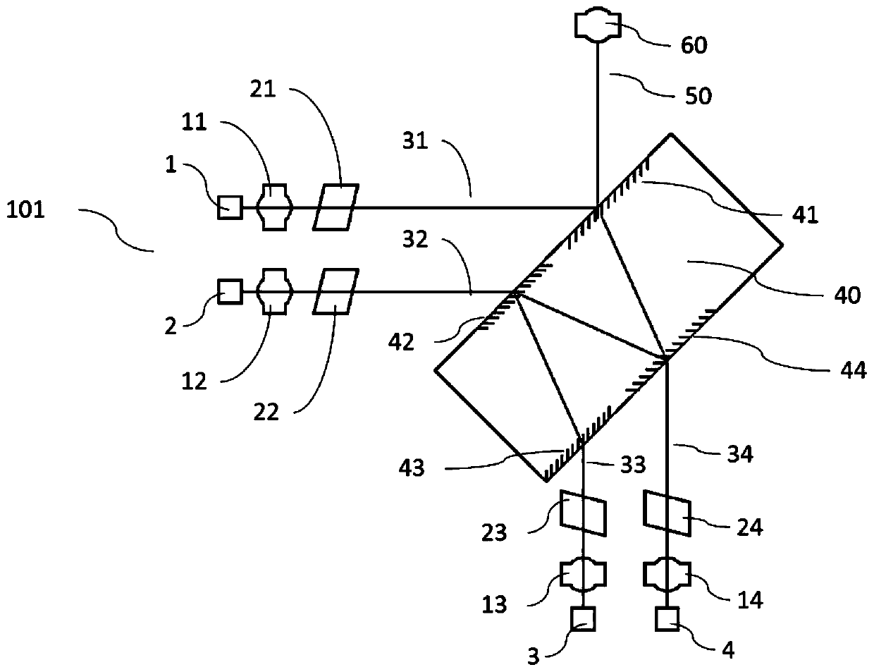
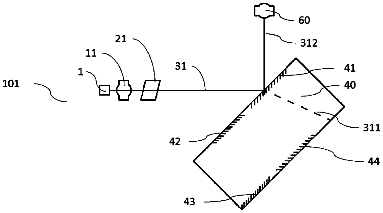
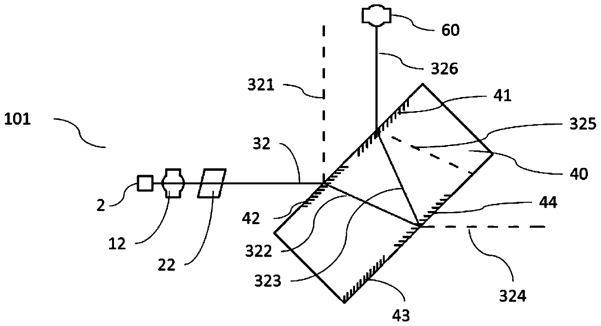
[0037] A multi-channel laser transmitter optical assembly 101 of the present invention is configured with four sets of lasers, four sets of collimating lenses, four sets of isolators, multiplexers and converging lenses.

[0038] From figure 1 As shown in the schematic diagram of Embodiment 1, the multi-channel laser transmitter optical assembly 101 has a first laser 1, a second laser 2, a third laser 3 and a fourth laser 4, which respectively generate a first optical signal 31 and a second optical signal 32 , the third optical signal 33 and the fourth optical signal 34 . The first and second optical signals are parallel to each other and exit horizontally, and the third and fourth optical signals are parallel to each other and exit vertically. The four groups of optical signals 31-34 are sent out by the four groups of lasers 1-4, respectively pass through the first collimating lens 11, the second collimating lens 12, the third collimating lens 13 and the fourth collimating le...


PUM


Abstract

The invention relates to the field of luminescent devices or optical signal transmitting devices, and provides a multichannel laser transmitter optical component comprising first to fourth sets of lasers which generate first to fourth sets of optical signals respectively. The first to fourth sets of optical signals enter into a combiner through first to fourth sets of collimating lenses and firstto fourth sets of isolators. The combiner is provided with first to fourth sets of diaphragms. The four diaphragms are partially transmitting and partially reflecting diaphragms of the specific size.The combiner combines the first to fourth sets of optical signals into one beam to be transmitted to the terminal through a conversion lens. According to the multichannel laser transmitter optical component, the four paths of optical signals of the multichannel laser transmitter optical component are combined into one beam at a lower cost, the combined optical signals have the same proportion withthe intensity of the optical signals before combination, combination of four different wavelengths of optical signals can be realized and combination of the four beams of optical signals of the samewavelength can also be realized.

Description

technical field [0001] The invention relates to the field of light emitting devices or optical signal emitting devices, in particular to a multi-channel light emitting device. Background technique [0002] In existing optical transceiver modules, the transmission rate of high-speed signals has been increased from hundreds of Mbps to tens of Gbps. After the single-channel optical transmission high-speed signal rate reaches a certain level, it is more common to increase the number of optical transmission channels to obtain a higher total transmission rate. [0003] Multi-channel technology has been applied to the optical interface of 40Gbps (4x10Gbps) and 100Gbps (4x25Gbps) transmission rate. The protocols of various transmission distances and various wavelengths of four channels are specified in the IEEE802.3 standard. Among them, the distance is 500 meters, 2 kilometers, 10 kilometers, etc., and the wavelength can also be the same wavelength (such as 1310nm) or different w...

Claims


Application Information

Patent Timeline
Patent Type & Authority Patents(China)
IPC IPC(8): G02B27/10
CPCG02B27/1006
Inventor 王昊王昌日张彩张舜张文臣
Owner DALIAN CANGLONG OPTOELECTRONICS TECH
Why Eureka
Try Eureka