Header for combine harvester

A technology for combine harvesters and headers, applied to harvesters, applications, cutters, etc., which can solve the problems of easy fatigue damage to parts on the right side of the header, large difference in vibration displacement between the left and right sides of the header, and increased loss of crop division. , to achieve the effect of reducing the loss of the right parting grain, reducing the fatigue damage and reducing the amplitude

Pending Publication Date: 2018-10-30
JIANGSU UNIV
View PDF7 Cites 6 Cited by
  • Summary
  • Abstract
  • Description
  • Claims
  • Application Information

AI Technical Summary

Problems solved by technology

[0003] In view of the large difference in the left and right vibration displacement of the header due to the offset of the conveying trough of the crawler combine harvester, the loss of the right side of the crop is significantly increased during harvesting, and the parts on the right side of the header are prone to fatigue damage and reduced service life. The invention provides a header for combine harvesters with different rigidity

Method used


Image

  • Header for combine harvester
  • Header for combine harvester
  • Header for combine harvester

Examples


Embodiment 1

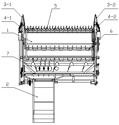
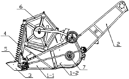
[0028] Example one: such as figure 1 As shown, a header for a combine harvester includes a header frame 1, a conveying trough 2, a crop divider 3, a double vertical cutter 4, a main cutter 5, a reel 6, and a screw conveyor 7 Conveying trough 2 is located at the rear left side of the forward direction of the header frame 1, and its center line is about 276mm-296mm from the left end of the header frame 1, and about 707mm-727mm from the right end of the header frame 1, 3 points for the grain divider It is the left crop divider 3-1 and the right crop divider 3-2, which are respectively arranged at the left front and right front of the forward direction of the rape header frame 1. The double vertical cutter 4 is divided into the left vertical cutter 4- 1 and the right vertical cutter 4-2, which are respectively arranged above the left crop divider 3-1 and the right crop divider 3-2. The main cutter 5 is located at the front end of the rape header frame 1 in the forward direction. Th...

Embodiment 2

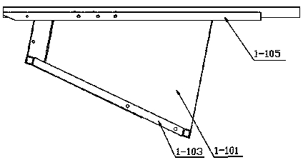
[0033] Embodiment 2: The composition of the parts of the header is exactly the same as in the first embodiment, but in order to realize that the rigidity of the components on the right side of the header frame 1 is greater than the stiffness of the components on the left side of the header frame 1, the supporting steel 1-107. The bottom connecting beam 1-207 and the steel 1-212 above the arc back plate are set in the form of variable cross-section with unequal stiffness to achieve the characteristics of unequal stiffness of the rape header.

Embodiment 3

[0034] Embodiment 3: The composition of the parts of the header is exactly the same as in the first embodiment, but in order to realize that the rigidity of the components on the right side of the header frame 1 is greater than the stiffness of the components on the left side of the header frame 1, the header frame 1 The left and right parts can be made of materials with different stiffness to achieve the characteristics of unequal stiffness of the rape header.


PUM


Abstract

The invention relates to a header for a combine harvester. The header mainly comprises a header rack, a conveying trough, a divider, two vertical cutters, a main cutter, a reel and a spiral conveyingauger. The conveying trough is connected to the left rear side of the header rack through bolts, the conveying trough serves as the standard, the portion, on the left side of the conveying trough, ofthe header rack is made of steel small in strength, and the portion, on the right side of the conveying trough, of the header rack is made of steel high in strength. Meanwhile, a right front supporting beam is welded to the right side of a bottom plate of the header rack, so that the problem that the conveying trough is located on the left side of the header and accordingly the amplitudes of the left vertical cutter and the right vertical cutter are obviously different is solved, and the dividing loss in the rapeseed harvesting process is reduced.

Description

Technical field [0001] The invention relates to a header for a combine harvester, belonging to the technical field of combine harvesters. Background technique [0002] At present, the types of crawler combine harvesters on the market are relatively single and their versatility is weak. In addition, the conveyor trough of the harvester and the header frame are mostly rigidly connected by bolts, and the delivery trough is located at the left rear of the header. For example, the utility model patent CN2247412Y discloses a harvester header frame including left and right side plates and the header The front beam, the rear plate of the header, the upper beam, the suspension pipe and the header outlet. The left and right side panels are of the whole board structure, and the header outlet is located at the right rear of the entire header; invention patent CN103828540B discloses a combine harvester The header includes a dustpan-shaped header frame, a cutter at the mouth of the dustpan, a...

Claims


Application Information

Patent Timeline
Patent Type & Authority Applications(China)
IPC IPC(8): A01D41/14
CPCA01D41/14
Inventor 徐立章张文涛李耀明
Owner JIANGSU UNIV
Why Eureka
Try Eureka