Onboard chassis with line-free design structure

A technology for designing structure and chassis, applied in the direction of chassis/cabinet/drawer parts, electrical equipment shell/cabinet/drawer, electrical components, etc. Line and maintenance, saving back space, and meeting the effect of vibration and shock requirements

Active Publication Date: 2018-10-30
BEIJING INST OF RADIO MEASUREMENT
View PDF11 Cites 4 Cited by
  • Summary
  • Abstract
  • Description
  • Claims
  • Application Information

AI Technical Summary

Problems solved by technology

Sometimes due to the limitation of the space elements of the carrier platform, the cables at the rear of the motherboard cannot meet the overall requirement

Method used


Image

  • Onboard chassis with line-free design structure
  • Onboard chassis with line-free design structure
  • Onboard chassis with line-free design structure

Examples


Embodiment 1

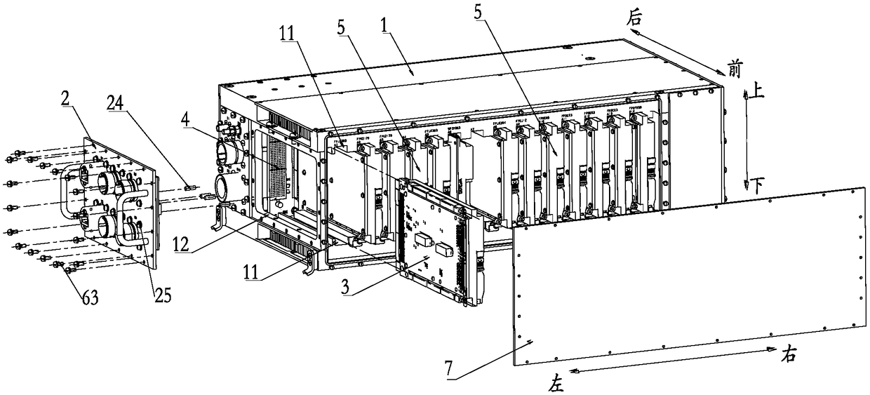
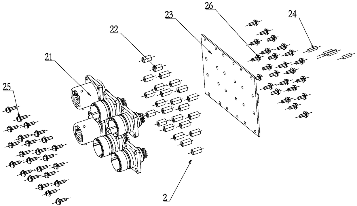
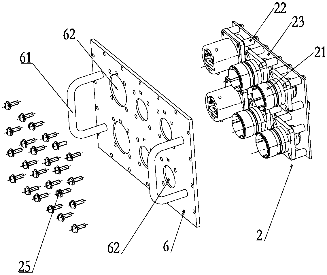
[0039] Such as Figure 1-Figure 5 As shown, an airborne chassis with a wire-free design structure in this embodiment includes an electronic chassis 1, an IO connector assembly 2, and a connector plug-in 3. A plug-in motherboard 4, a number of electronic Plug-in 5 and some electronic devices, some of the electronic plug-ins 5 are connected to the front side of the plug-in motherboard 4, and some of the electronic devices are connected to the rear side of the plug-in motherboard 4, and the IO connector assembly 2 is installed At one end of the electronic chassis 1; a slot 11 is reserved near the end of the IO connector assembly 2 in the electronic chassis 1, and the plug-in motherboard 4 and the IO connector assembly 2 are all connected to the slot The position 11 is connected, and the connector insert 3 is plugged into the slot 11 and connected with the IO connector assembly 2 and the insert motherboard 4 respectively to realize signal transfer.

[0040] In this embodiment, th...

Embodiment 2

[0043] Such as Figure 1-Figure 5As shown, an airborne chassis with a wire-free design structure in this embodiment includes an electronic chassis 1, an IO connector assembly 2, and a connector plug-in 3. A plug-in motherboard 4, a number of electronic Plug-in 5 and some electronic devices, some of the electronic plug-ins 5 are connected to the front side of the plug-in motherboard 4, and some of the electronic devices are connected to the rear side of the plug-in motherboard 4, and the IO connector assembly 2 is installed At one end of the electronic chassis 1; a slot 11 is reserved near the end of the IO connector assembly 2 in the electronic chassis 1, and the plug-in motherboard 4 and the IO connector assembly 2 are all connected to the groove. The position 11 is connected, and the connector insert 3 is plugged into the slot 11 and connected with the IO connector assembly 2 and the insert motherboard 4 respectively to realize signal transfer. Among them, the connector plu...


PUM


Abstract

The invention relates to an onboard chassis with a line-free design structure, which comprises an electronic chassis, an IO connector assembly and a connector plug-in, wherein a plug-in motherboard, aplurality of electronic plug-ins and a plurality of electronic devices are mounted in the electronic chassis; a plurality of the electronic plug-ins are connected on the front side of the plug-in motherboard; a plurality of electronic devices are connected on the rear side of the plug-in motherboard; the IO connector assembly is mounted at one end of the electronic chassis; a slot position is reserved at one end of the electronic chassis close to the IO connector assembly; both the plug-in motherboard and the IO connector assembly communicate with the slot position; the connector plug-in is plugged at the slot position and is respectively connected with the IO connector assembly and the plug-in motherboard to achieve signal transfer. According to the onboard chassis with a line-free design structure in the invention, the connector plug-in is arranged, so that signal transfer between the plug-in motherboard and the IO connector assembly is realized, and the problem of internal wiring and maintenance of the high-density integrated onboard chassis can be effectively solved.

Description

technical field [0001] The invention relates to a wire-free design structure on an airborne chassis, in particular to an airborne chassis with a wire-free design structure. Background technique [0002] The airborne electronic chassis has extremely high requirements for the size and weight of the equipment due to the use environment of the upper-mounted aircraft. Lightweight and miniaturized is the development trend of airborne electronic equipment. Due to the tight space elements, the traditional wire-welded wiring form inside the chassis cannot meet the wiring design requirements, and a wire-free design structure is required. At the same time, reducing the number of cables inside the chassis can indirectly reduce the overall size and weight of the chassis and improve the reliability of the device. [0003] At this stage, the cable-free design structure of the airborne chassis generally transmits signals through the adapter board installed at the rear of the chassis mother...

Claims


Application Information

Patent Timeline
IPC IPC(8): H05K5/02
CPCH05K5/0247
Inventor 骆德军
Owner BEIJING INST OF RADIO MEASUREMENT
Why Eureka
Try Eureka