
A high-efficiency relief valve

An overflow valve, high-efficiency technology, applied in the direction of fluid pressure actuation device, servo motor assembly, mechanical equipment, etc., can solve the problem that the spring compression is not proportional to the elastic force, it is difficult, and cannot achieve rapid overflow, etc. The effect of a large reaction speed

Active Publication Date: 2019-11-01
JIANGSU XIYI HIGH NEW DISTRICT TECH DEV CO LTD
View PDF1 Cites 0 Cited by
  • Summary
  • Abstract
  • Description
  • Claims
  • Application Information

AI Technical Summary

Problems solved by technology

[0004] This technical solution can adjust the opening pressure of the pressure valve; but in this solution, it is realized by adjusting the compression amount of the spring, but the compression amount of the spring is not proportional to the elastic force, and it is difficult to achieve a certain amount of compression. Get a certain pressure value; when the pressure valve is used as a relief valve, it cannot achieve rapid relief

Method used


Image

  • A high-efficiency relief valve
  • A high-efficiency relief valve
  • A high-efficiency relief valve

Examples


Embodiment Construction

[0022] In order to make the technical means, creative features, goals and effects achieved by the present invention easy to understand, the present invention will be further described below in conjunction with specific embodiments.

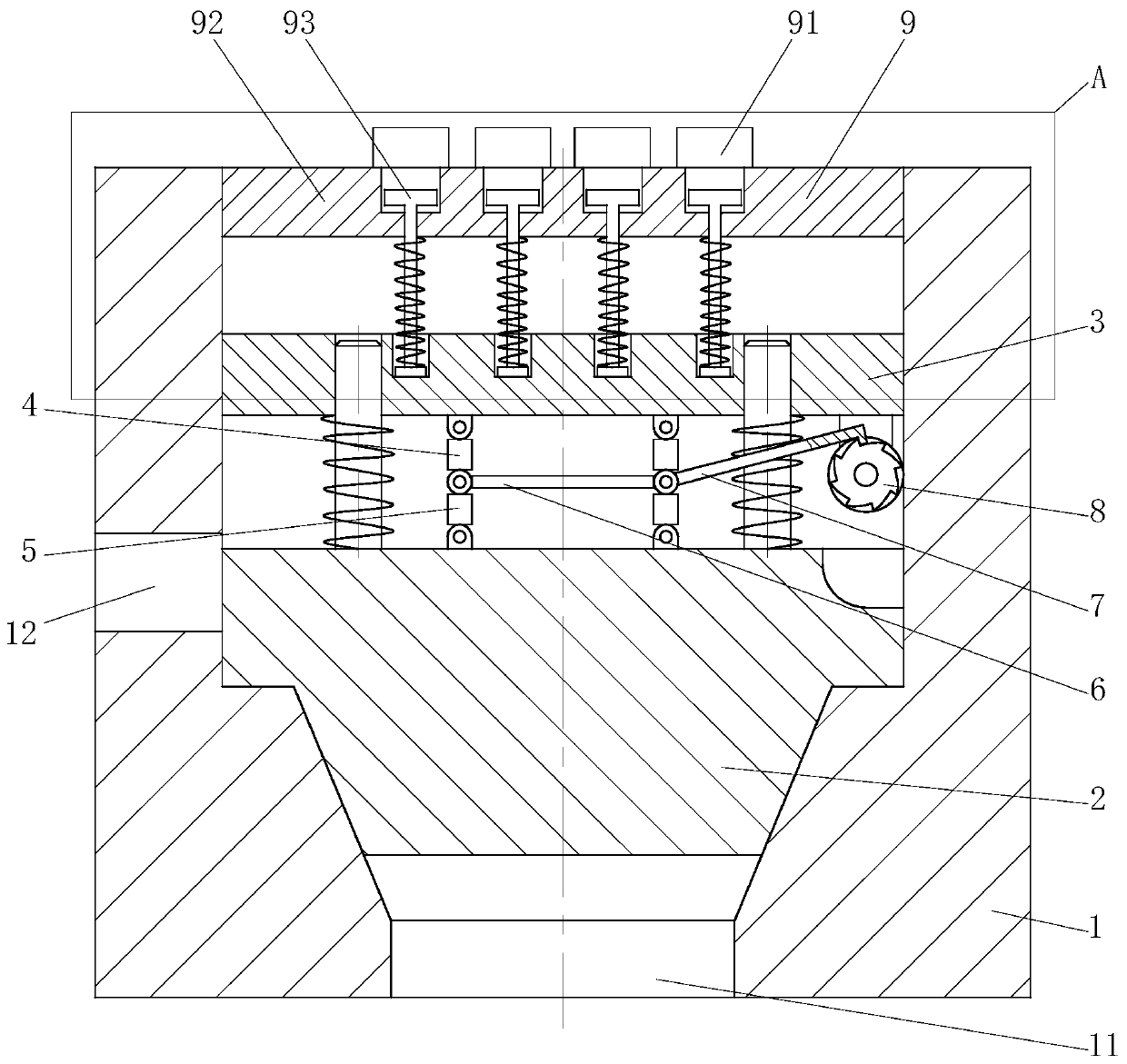
[0023] Such as Figure 1 to Figure 5As shown, a high-efficiency relief valve according to the present invention includes a valve body 1, a cavity is arranged inside the valve body 1, an oil inlet hole 11 is arranged at the lower end of the valve body 1, and an oil outlet is arranged on the cylindrical surface of the middle part of the valve body 1. Hole 12; high-efficiency relief valve also includes movable spool 2, spool support plate 3, guide post, No. 1 support rod 4, No. 2 support rod 5, connecting rod 6, pull rod 7, friction wheel 8, elastic module 9, The movable spool 2 is slidably installed in the cavity of the valve body 1; one end of a group of guide posts is fixedly connected to the upper end surface of the movable spool 2; the other end...


PUM


Abstract

The invention belongs to the technical field of valves, and particularly relates to an efficient overflow valve. The efficient overflow valve comprises a movable valve element, a valve element supporting plate, a guide column, a first supporting rod, a second supporting rod, a connecting rod, a pull rod, a friction wheel and an elastic module, wherein the lower end face of the valve element supporting plate is connected with the upper end face of the movable valve element through the first supporting rod and the second supporting rod, and one end of a pull rod is hinged to the hinge joint of the first support rod and the second support rod at the same time, close to the inner wall, of the valve body; and a pawl is arranged at the other end of the pull rod, the cylindrical face of a friction wheel is in contact with the inner wall of the cavity of the valve body, the elastic module is arranged above the valve element supporting plate, and the elastic module is used for applying elasticity to the valve element supporting plate. According to the valve, the pull rod is driven by a ratchet wheel arranged on the friction wheel to move, the pull rod drives the first supporting rod and thesecond supporting rod to swing, so that the movable valve element can be quickly moved upwards, and then the oil passage between an oil inlet hole and an oil outlet hole is conducted, and finally fast overflow of the overflow valve is realized.

Description

technical field [0001] The invention belongs to the technical field of valves, in particular to a high-efficiency overflow valve. Background technique [0002] In the hydraulic transmission system, the hydraulic valve that controls the oil pressure level is called a pressure control valve, referred to as a pressure valve. The common point of this type of valve is mainly to use the principle of balancing the hydraulic pressure on the valve core and the spring force to work. Yes, the existing pressure valve is mainly composed of valve body, valve cover, valve disc and spring, and most pressure valves use a fixed number of springs to realize the constant pressure of the pressure valve, which can only control one pressure. When changing, it is necessary to use other pressure valves with different pressure values, which will lead to an increase in cost and inconvenient operation. Relief valve is a kind of hydraulic pressure control valve, which mainly plays the role of constant ...

Claims


Application Information

Patent Timeline
Patent Type & Authority Patents(China)
IPC IPC(8): F15B13/02
CPCF15B13/021
Inventor 邢箫
Owner JIANGSU XIYI HIGH NEW DISTRICT TECH DEV CO LTD
Learn More