Continuously variable transmission

A continuously variable transmission and variable displacement technology

Inactive Publication Date: 2018-11-02
HEFEI CHUANGYUAN VEHICLE CONTROL TECH
View PDF5 Cites 1 Cited by
  • Summary
  • Abstract
  • Description
  • Claims
  • Application Information

AI Technical Summary

Problems solved by technology

Belt (or chain) continuously variable transmission CVT has the advantages of continuously adjustable speed ratio, good smoothness, small and simple structure, and the disadvantage is that it requires high manufacturing process and it is difficult to transmit large torque; the roller turntable continuous continuously variable transmission IVT, Composed of discs and rollers, the structure is simple, but the friction between the discs and rollers causes large energy loss, temperature rise, and low product reliability
[0003] In the field of engineering vehicles, for example, in the hydraulic drive travel system of excavators and forklifts, the travel system is composed of separate hydraulic pumps and hydraulic motors, the system structure is complicated, the cost is high, and the efficiency is low
[0004] In the field of high-speed engineering vehicles, the main reason for its high-speed limitation is that the separation and coordination of the hydraulic pump and hydraulic motor in the hydraulic drive travel system cannot meet the requirements of high-speed travel.

Method used


Image

  • Continuously variable transmission
  • Continuously variable transmission
  • Continuously variable transmission

Examples


Embodiment 1

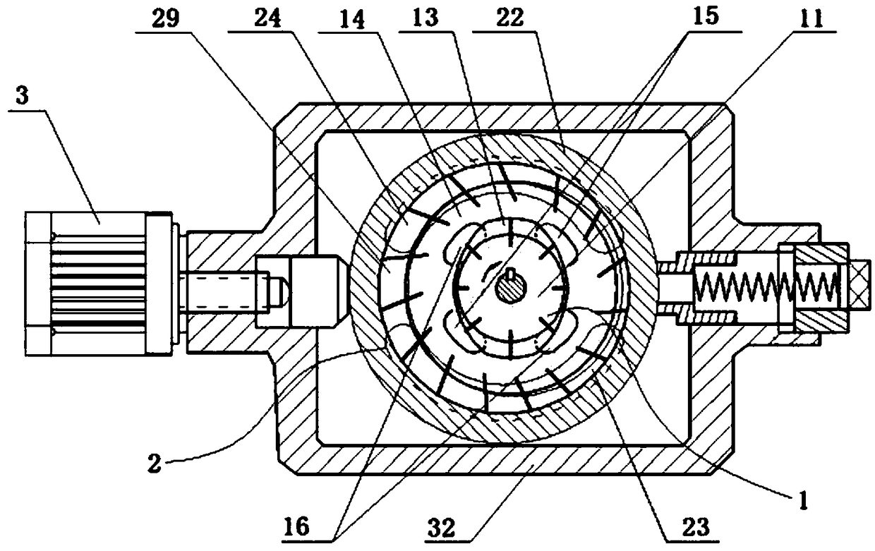
[0052] See image 3, a continuously variable transmission, including a fixed-displacement pump 1 and a variable-displacement motor 2, the fixed-displacement pump 1 is a double-vane fixed-displacement pump, the variable-displacement motor 2 is a single-vane variable-displacement motor, and the double-vane fixed The displacement pump is mainly composed of an inner rotor 11, a common rotor 14, and a cavity 13. The center of circle of the double-blade fixed-displacement pump 1 is fixed relative to the position of the housing 32; the single-blade variable displacement motor is mainly composed of the common rotor 14, The stator 22 and the cavity 29 are composed. The stator 22 of the single-vane variable displacement motor can move radially under the action of the eccentric adjustment mechanism 3, thereby changing the liquid intake volume of the single-vane variable displacement motor, that is, the displacement V2. The inner rotor 11 of the double vane fixed displacement pump is the ...

Embodiment 2

[0056] See Figure 4 and Figure 5 , a continuously variable transmission, including a fixed-displacement pump 1 and a variable-displacement motor 2, the fixed-displacement pump 1 is a double-vane quantitative liquid pump, the variable-displacement motor 2 is a single-acting variable-vane motor, and the double-vane quantitative liquid pump and the single-acting variable vane motor is an axial layout structure, 3 is the eccentric adjustment mechanism, 18 is the low-pressure inlet of the double-vane quantitative liquid pump, 19 is the high-pressure outlet of the double-vane quantitative liquid pump, 25 is the high-pressure liquid input port of the motor, 26 12 is the outer rotor of the double vane quantitative liquid pump, 21 is the inner rotor of the single-acting variable vane motor, 27 is the spline sleeve connecting the motor and the pump, and 17 is the spline connecting the pump and the motor Shaft, 37 is a high-pressure rotary sealing ring, 38 is a high-pressure channel o...

Embodiment 3

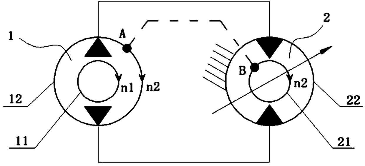
[0060] See Image 6 , a continuously variable transmission, including a variable displacement pump 5 and a variable displacement motor 2, the outer rotor (point A) of the variable displacement pump 5 is rigidly connected with the inner rotor (point B) of the variable displacement motor 2, 51 is The inner rotor of the variable displacement pump, 52 is the outer rotor of the variable displacement pump, 21 is the inner rotor of the variable displacement motor, 22 is the stator of the variable displacement motor, the stator 22 of the variable displacement motor is connected with the casing, and the The power input is added to the inner rotor 51 of the variable displacement pump 5, and the outer rotor 52 of the variable displacement pump 5 outputs power.

[0061] The power direction of the inner rotor 51 of the variable displacement pump is set to be clockwise, and the direction of the force of the high pressure oil input by the variable displacement motor 2 acting on the inner rot...


PUM


Abstract

The invention discloses a continuously variable transmission. The continuously variable transmission comprises a pump and a motor, the pump is a constant displacement pump or a variable displacement pump, the motor is a fixed displacement motor or a variable displacement motor, and at least one of the pump and the motor is a variable displacement structure; and a high-pressure input port of the motor communicates with a high-pressure output port of the pump, a low-pressure input port of the pump communicates with a low-pressure output port of the motor, an inner rotor of the pump is power input, an outer rotor of the pump is power output, and the outer rotor of the pump and an inner rotor of the motor are of a rigid connection structure or a rigid integrated structure. According to the continuously variable transmission, due to the fact that the rotating torque borne by the outer rotor of the pump and the output torque of the motor are output in an overlapping mode, the system efficiency and the output rotating speed are greatly improved, when the rotating torque required by the load is close to the rotating torque of the inner rotor of the pump, the output rotating speed of the continuously variable transmission is close to the input rotating speed, and the efficiency of the continuously variable transmission is close to 100%.

Description

technical field [0001] The invention relates to the field of mechanical variable speed transmission, in particular to a continuously variable transmission, especially to the field of vehicle continuously variable transmission. Background technique [0002] The vehicle transmission has been pursuing a more perfect continuously variable transmission. An ideal transmission can match the load of the vehicle and the dynamic characteristics of the engine continuously and in real time. The main forms of continuously variable transmissions equipped on vehicles are belt (or chain) continuously variable transmissions (CVT) and roller rotary disc type continuous infinite transmissions (IVT). Belt (or chain) continuously variable transmission CVT has the advantages of continuously adjustable speed ratio, good smoothness, small and simple structure, and the disadvantage is that it requires high manufacturing process and it is difficult to transmit large torque; the roller turntable conti...

Claims


Application Information

Patent Timeline
Patent Type & Authority Applications(China)
IPC IPC(8): F16H39/42
CPCF16H39/42
Inventor 袁廷华
Owner HEFEI CHUANGYUAN VEHICLE CONTROL TECH
Why Eureka
Try Eureka