A structure and method for optical measurement of front and rear binocular position and attitude

An optical measurement and attitude technology, which is applied in the directions of measuring devices, measuring angles, surveying and navigation, etc., can solve problems such as inability to directly measure inclination angles, achieve the effects of improving measurement accuracy and reliability, high imaging quality, and eliminating influence errors

Active Publication Date: 2020-09-11
武汉环汉机电工程技术有限公司
View PDF5 Cites 0 Cited by
  • Summary
  • Abstract
  • Description
  • Claims
  • Application Information

AI Technical Summary

Problems solved by technology

[0006] The measurement method of beam drift compensation with collimated laser plus CCD [The OT-7000Auto-Centering, Wireless, Multi-Target Alignment. On-Trak Photonics, Inc., 2017] is a narrow Measuring instrument for position in a long space cross-section, additional CCD measuring beam drift and compensation, the measurement process along the straight line reference allows intermediate interruptions, but cannot directly measure the inclination angle
[0007] Micrometric magnifying glass [Lei Jianqiang, Application of micrometer level in tunnel vault sinking measurement, Modern Tunnel Technology, 2012, Vol.49(1), 171-174] is a kind of narrowing lens based on the principle of collimating telescope. Measuring instrument for position in a long spatial cross-section, the measurement process along a straight line datum allows intermediate interruptions, but does not directly measure inclination

Method used


Image

  • A structure and method for optical measurement of front and rear binocular position and attitude
  • A structure and method for optical measurement of front and rear binocular position and attitude
  • A structure and method for optical measurement of front and rear binocular position and attitude

Examples


Embodiment Construction

[0045] In order to make the object, technical solution and advantages of the present invention clearer, the present invention will be further described in detail below in conjunction with the accompanying drawings and embodiments. It should be understood that the specific embodiments described here are only used to explain the present invention, not to limit the present invention. In addition, the technical features involved in the various embodiments of the present invention described below can be combined with each other as long as they do not constitute a conflict with each other.

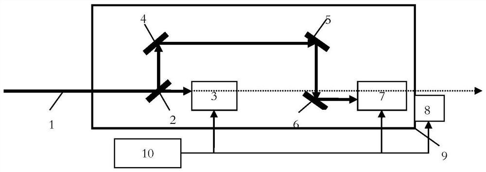
[0046] figure 1 It is a schematic diagram of the structure and optical path of a front and rear dual-purpose position and posture optical measurement structure of the present invention; figure 1 As shown, the front and rear binocular position and posture optical measurement structure includes a collimated light beam 1, a beam splitter 2, a front optical sensor 3, a first reflector 4, a second r...


PUM


Abstract

The invention discloses a front and rear binocular position and attitude optical measurement structure. The structure comprises a collimation light beam (1) and a frame (9), wherein a front optical sensor (3) and a rear optical sensor (7) are arranged in the frame (9) along the incident direction of the collimation light beam (1), the frame (9) is further internally provided with a beam splitter (2), a first reflector (4), a second reflector (5) perpendicular to the first reflector (4) and a third reflector (6) which is parallel to the second reflector (5) and is between the front optical sensor (3) and the rear optical sensor (7), and photosensitive surfaces of the front optical sensor (3) and the rear optical sensor (7) are parallel to the axis of a to-be-measured object. The invention further discloses a front and rear binocular position and attitude optical measurement method. The front and rear binocular position and attitude optical measurement structure is advantaged in that narrow long hole position and attitude measurement is achieved.

Description

technical field [0001] The invention belongs to the technical field of optical image measurement for shape and position measurement of manufactured parts, and more specifically relates to a structure and method for optical measurement of position and posture with front and rear dual purposes. Background technique [0002] Optical image measurement technology, that is, visual measurement and positioning technology, uses the image captured by the camera as the information carrier, extracts the useful information in the image through computer technology, and then analyzes and summarizes the information to obtain the measurement result, which has all-round rapid measurement and positioning , high precision and strong real-time characteristics, so it is widely used in various measurement tasks. [0003] Existing studies have shown that when the relative inclination angle between the journal and the bushing of a hydraulic radial bearing increases from 0 to 0.0002 radians, the perf...

Claims


Application Information

Patent Timeline
Patent Type & Authority Patents(China)
IPC IPC(8): G01B11/00G01C1/00
CPCG01B11/002G01C1/00
Inventor 张新宝
Owner 武汉环汉机电工程技术有限公司
Why Eureka
Try Eureka