Eureka AIR delivers breakthrough ideas for toughest innovation challenges, trusted by R&D personnel around the world.

Flexible capacitive-type pressure sensor and preparation method therefor

A technology of pressure sensor and flexible capacitor, which is applied in the field of microelectronics, can solve the problems of small pressure measurement range and poor linear characteristics, and achieve the effect of improving dielectric gauge factor, improving sensitivity, improving dynamic range and linearity

Pending Publication Date: 2018-11-02
NANJING UNIV OF TECH
View PDF10 Cites 14 Cited by
  • Summary
  • Abstract
  • Description
  • Claims
  • Application Information

AI Technical Summary

Benefits of technology

This new type of device uses three dimensional (3D) printers that create precise holes within it's materials for better performance or more accurate measurements compared with previous methods like laser drilling techniques. By controlling these dimensions accurately, this device has improved ability to measure small changes caused by external factors such as temperature variations over time without losing accuracy due to thermal expansion issues affecting its functioning properly.

Problems solved by technology

Technological Problem addressed in this patented technical paper describes different ways how to improve flexibility and durability of electronic components such as touch screens used at various locations like outdoors without being visible due to their opaque nature. Existing methods involve increasing rigidity and reducing weight, making them difficult to use in practical situations where there may also be environmental concerns associated with disposables containing harmful chemical agents. There is an urgent demand for improved flexible pressure sensor technology capable of detecting smaller pressures within wide ranges despite having excellent mechanical performance and usages potential.

Method used


Image

  • Flexible capacitive-type pressure sensor and preparation method therefor
  • Flexible capacitive-type pressure sensor and preparation method therefor
  • Flexible capacitive-type pressure sensor and preparation method therefor

Examples


Embodiment 1

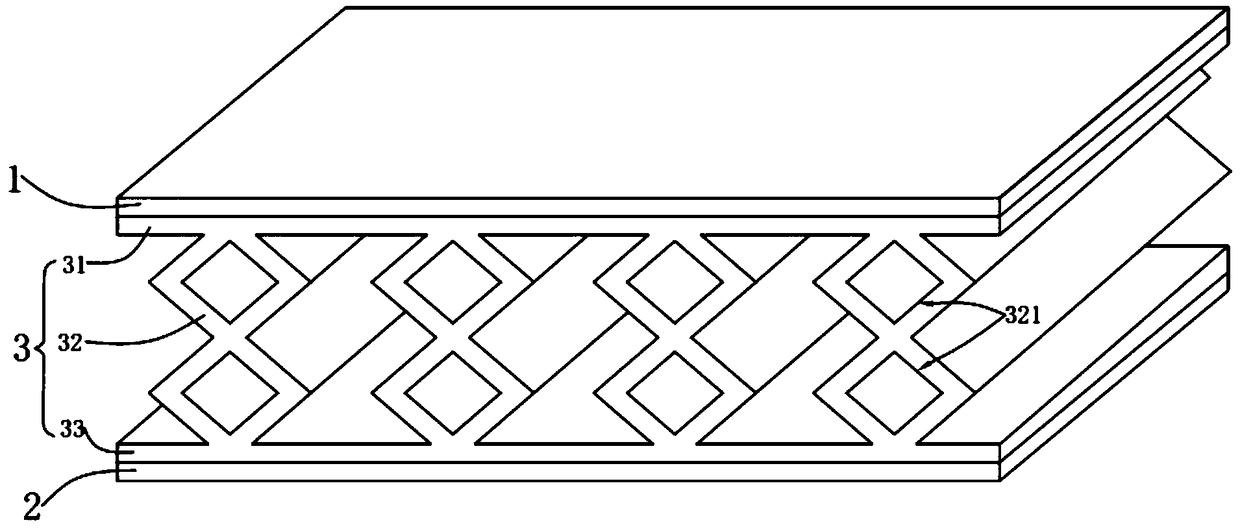
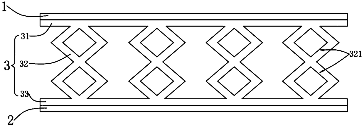
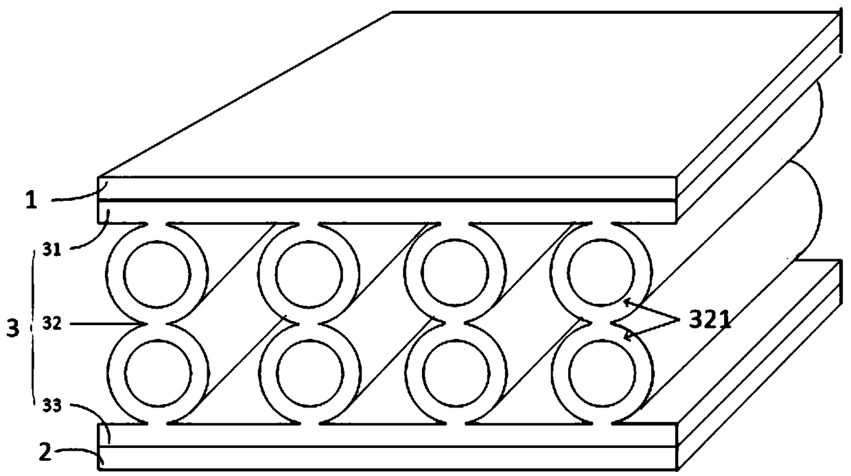
[0032] refer to figure 1 , the present invention provides a flexible capacitive pressure sensor, the flexible capacitive pressure sensor includes an upper electrode 1, a lower electrode 2 and a composite dielectric layer 3 sandwiched between the upper electrode 1 and the lower electrode 2, wherein the upper electrode 1 Both the electrode and the lower electrode 2 are flexible planar plates; the composite dielectric layer 3 has a topological structure.

[0033] Specifically, such as figure 2 As shown, the composite dielectric layer 3 includes a first structural layer 31 connected to the upper electrode 1 , a second structural layer 33 connected to the lower electrode 2 , a deformable layer disposed between the first structural layer 31 and the second structural layer 33 Layer 32, the first structural layer 31 is a flexible planar plate corresponding to the upper electrode 31, and the second structural layer 33 is a flexible planar plate corresponding to the lower electrode 2;...

Embodiment 2

[0037] refer to Figure 5 and Image 6 , the present invention also provides a preparation method for the flexible capacitive pressure sensor of embodiment 1, specifically comprising:

[0038] Prepare to form the upper mold 4 of composite dielectric layer and the lower mold 5 ( Figure 5 with Image 6 , the shaded part indicated by the slash is the upper mold, and the shaded part indicated by the grid is the lower mold), specifically, the upper mold 4 and the lower mold 5 can be prepared by 3D printing technology, combined by snap-fitting, along the bayonet Assembling the upper mold 4 and the lower mold 5 into a complete composite dielectric layer mold with a topological structure, wherein the upper mold 4 includes a plurality of first columns arranged at intervals and a first cavity surrounding the first columns; The lower mold 5 includes a plurality of second cylinders arranged at intervals and a second cavity around the second cylinders. The cross-sections of the first cyl...


PUM


Abstract

The invention provides a flexible capacitive-type pressure sensor, and the sensor comprises an upper electrode, a lower electrode, and a composite dielectric layer disposed between the upper electrodeand the lower electrode. The composite dielectric layer comprises a first structure layer connected with the upper electrode, a second structure layer connected with the lower electrode, and a deformable layer disposed between the first structure layer and the second structure layer. The deformable layer has a topological structure. Compared with the prior art, the senor structure based on the 3Dprinting technology precisely controls the size and distribution of holes in a pressure-sensitive material, and improves the dynamic range and linearity of the sensor. The setting of the deformable structure of the composite dielectric layer enables the characteristics of the dielectric strain effect to be fully utilized, thereby improving the dielectric strain coefficient of the dielectric material, and further improving the sensitivity of the sensor.

Description


Claims


Application Information

Patent Timeline
Owner NANJING UNIV OF TECH
Why Eureka
Eureka Blog
Learn More