Cable switching device

A transfer device and cable technology, applied in the directions of cable joints, connections, conductive connections, etc., can solve problems such as cable disconnection in the transfer box, and achieve the effects of avoiding disconnection, avoiding back-off, and improving stability.

Active Publication Date: 2018-11-02
重庆国翰能源发展有限公司
View PDF2 Cites 4 Cited by
  • Summary
  • Abstract
  • Description
  • Claims
  • Application Information

AI Technical Summary

Problems solved by technology

[0003] Aiming at the deficiencies in the prior art, the purpose of the present invention is to provide a cable transfer device to solve the problems in the prior art that the cables in the transfer box are prone to appear due to the shaking of the cables under the action of external force. open circuit problem

Method used


Image

  • Cable switching device
  • Cable switching device
  • Cable switching device

Examples


Embodiment

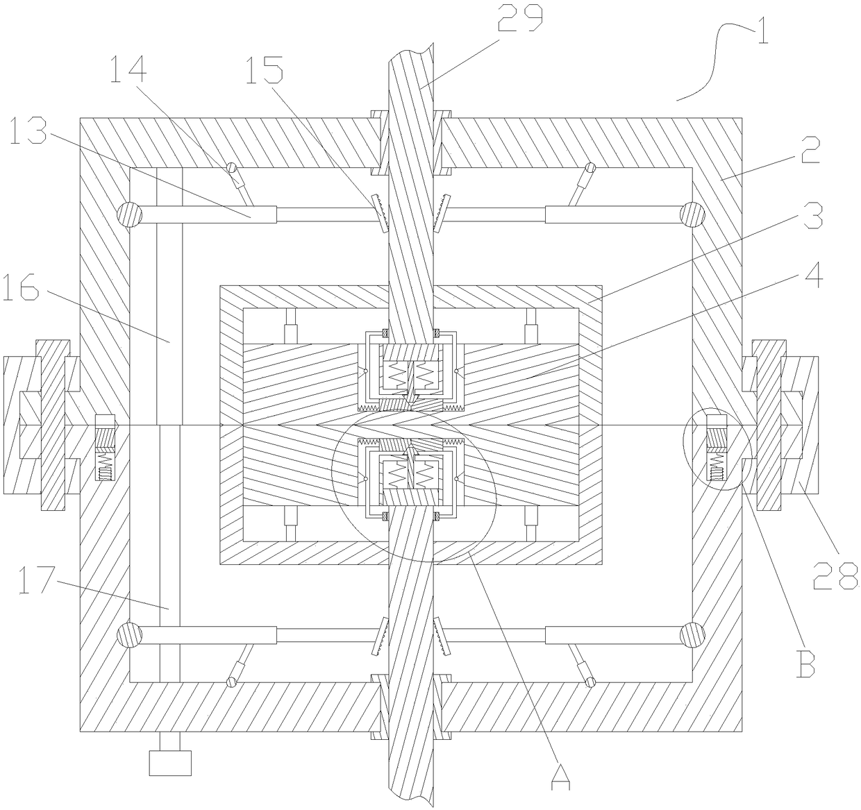
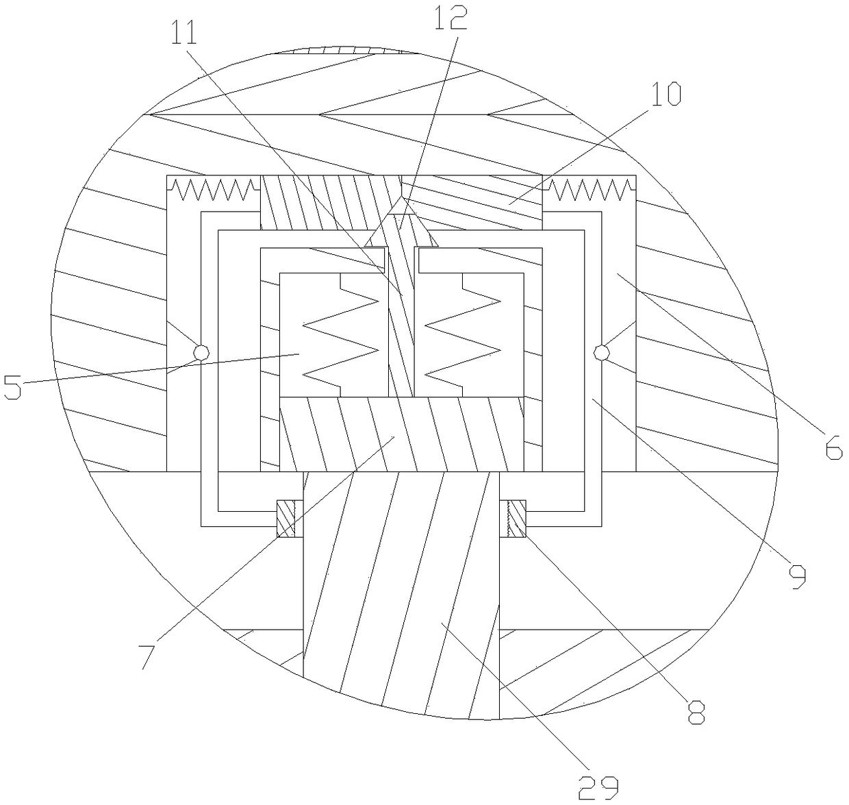
[0018] refer to Figure 1 ~ Figure 4 Shown: a cable transfer device, including two connecting seats 1 arranged symmetrically, the two connecting seats 1 are detachably sealed and connected to form a transfer box, and each connecting seat 1 includes a shell 2 with an opening at one end The inner wall of the casing 2 is fixed with a setting groove 3, the opening of the setting groove 3 is on the same side as the opening of the casing 2, and the conductive block 4 is arranged in the setting groove 3 through a plurality of retractable rods, and the casing 2 and the setting There are cable 29 penetration holes on the groove 3, and the cables 29 are electrically connected with the conductive block 4 after passing through the two cable 29 penetration holes in turn; The housing 2 is provided with an anti-retraction mechanism that prevents the cable 29 from retreating so that the cable 29 is disconnected from the conductive block 4; The "U" shaped groove 6 on the outside of the slidin...


PUM


Abstract

The invention discloses a cable switching device, comprising two connecting seats, wherein each connecting seat comprises a shell, a setting groove is fixed on the inner wall of the shell, a conductive block is arranged in the setting groove, and a cable is electrically connected to the conductive block after sequentially penetrating through two cable penetration holes; a clamping mechanism is arranged in the setting groove; a conductive sliding block is slidably arranged in a sliding groove, the clamping mechanism comprises two clamping rings, and each of the clamping rings is provided with aswing rod assembly; each swing rod assembly comprises a swing rod, one end of each swing rod is connected with the clamping ring, the other end of each swing rod is connected with a wedge block, an ejector rod assembly is arranged between the two wedge blocks, the ejector rod assembly comprises an ejector rod that is connected with the conductive block and penetrates through a communication holeand a top block that is connected to the ejector rod and penetrates out of the end part of the sliding groove, the top block is in the shape of isosceles trapezoid, and two oblique sides of the top block are slidably abutted against the wedge surfaces of the two wedge blocks respectively. Compared with the prior art, by adopting the scheme of the invention, the stability performance of the cablesafter connection can be improved, and the line can be maintained in a normal state for a long time.

Description

technical field [0001] The invention relates to the technical field of power cables, in particular to a cable transfer device. Background technique [0002] During the cable laying process, when connecting two cables, a transfer box is usually used for connection. Because the cables are laid overhead, the cables are easy to shake under the action of external force, resulting in The cable is prone to open circuit problems, which affects the use of the line. Contents of the invention [0003] Aiming at the deficiencies in the prior art, the purpose of the present invention is to provide a cable transfer device to solve the problems in the prior art that the cables in the transfer box are prone to appear due to the shaking of the cables under the action of external force. circuit breaker problem. [0004] In order to achieve the above object, the present invention adopts the following technical solution: a cable transfer device, including two connecting seats with symmetric...

Claims


Application Information

Patent Timeline
Patent Type & Authority Applications(China)
IPC IPC(8): H01R11/09H01R11/01H01R4/50H02G15/10
CPCH01R4/5083H01R11/01H01R11/09H02G15/10
Inventor 刘崇汉朱晓峰
Owner 重庆国翰能源发展有限公司
Why Eureka
Try Eureka