Filter bag fixing mechanism for pulse-jet bag dust collector

A bag-type dust collector and fixed mechanism technology, applied in the fields of dispersed particle filtration, chemical instruments and methods, dispersed particle separation, etc., can solve the problems of affecting the dust removal effect, reducing the service life, increasing the load of the dust collector, etc., so as to avoid mutual The effect of friction, prolonging service life and avoiding secondary adsorption

Inactive Publication Date: 2018-11-06
芜湖若科自动化科技有限公司
View PDF4 Cites 0 Cited by
  • Summary
  • Abstract
  • Description
  • Claims
  • Application Information

AI Technical Summary

Problems solved by technology

During the filtering and dust cleaning process of the bag filter, due to the irregular flow of the air flow, the cage and the filter bag shake violently, especially the lower part is larger, causing mutual friction between the filter bags, especially in the dust collector. When filtering, due to the negative pressure of the filter bag, it is in a deflated state, coupled with the effect of the updraft, the cage is often lifted, which increases the folding range of the filter bag, reduces the service life, and affects the dust removal effect
At the same time, the continuous shaking of the filter bag and the cage frame also makes it difficult for the dust to settle, prolonging the settling time of the dust, especially for the dust with fine particles and strong viscosity, it is easy to cause secondary adsorption and increase the load of the dust collector , affecting the normal operation of the bag filter

Method used


Image

  • Filter bag fixing mechanism for pulse-jet bag dust collector
  • Filter bag fixing mechanism for pulse-jet bag dust collector

Examples


Embodiment Construction

[0017] The following will clearly and completely describe the technical solutions in the embodiments of the present invention with reference to the accompanying drawings in the embodiments of the present invention. Obviously, the described embodiments are only some, not all, embodiments of the present invention. Based on the embodiments of the present invention, all other embodiments obtained by persons of ordinary skill in the art without making creative efforts belong to the protection scope of the present invention.

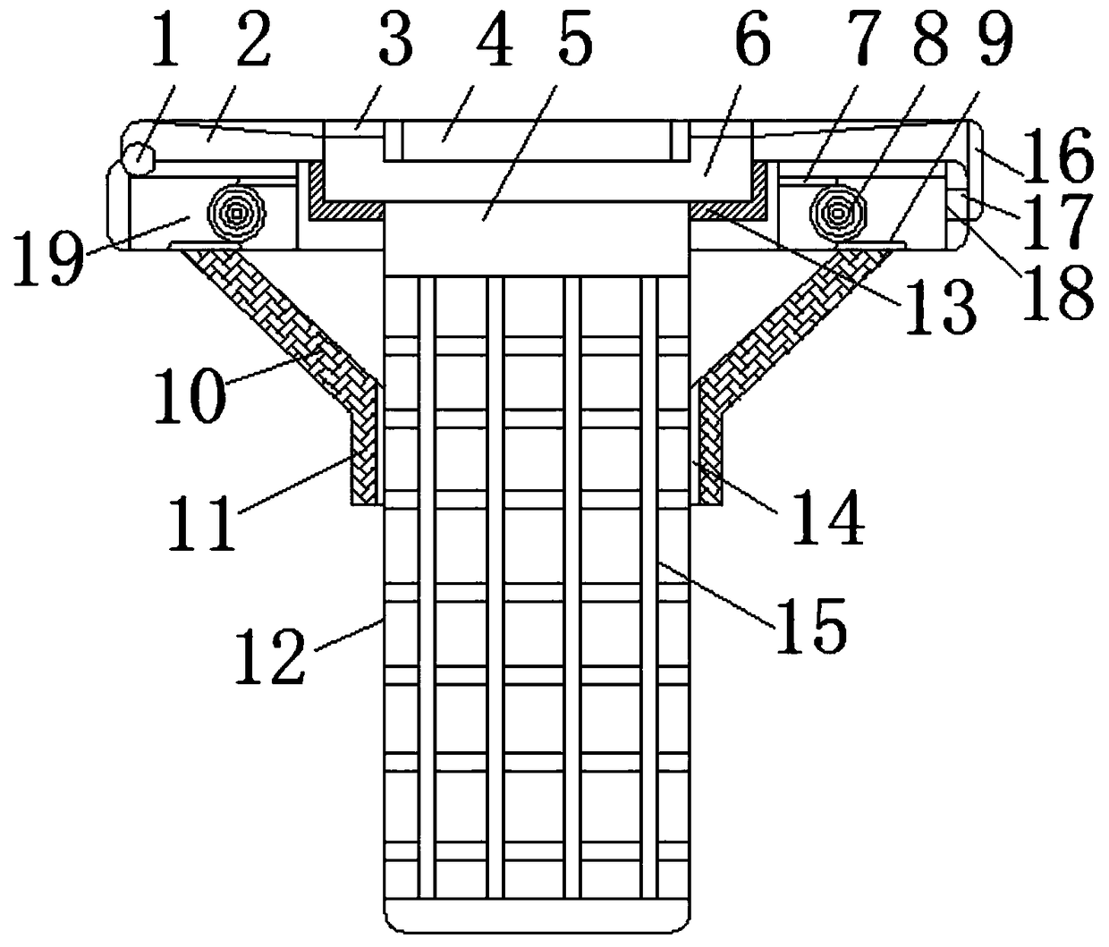
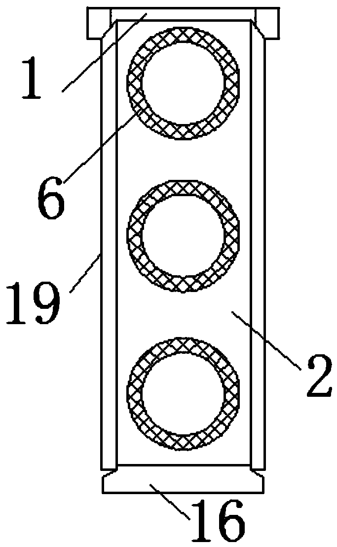
[0018] see Figure 1-2 , the present invention provides a technical solution: a filter bag fixing mechanism for a pulse bag filter, including a pressure plate 2, the pressure plate 2 is movably connected to the top end of the flower plate 19 through a rivet 1, and the middle of the flower plate 19 A groove 13 is opened, a positioning head 5 is pierced in the middle of the groove 13, an annular groove 6 is arranged on the top of the positioning head 5, and a pr...


PUM


Abstract

The invention discloses a filter bag fixing mechanism for a pulse-jet bag dust collector. The filter bag fixing mechanism comprises a pressing plate, wherein the pressing plate is movably connected toone end of the top of a pattern card by virtue of rivets; a groove is formed in the middle of the pattern card; a positioning head penetrates through the middle of the groove; an annular groove is formed in the top of the positioning head; a pressure block corresponding to the annular groove is welded at the bottom of the pressing plate; through holes are correspondingly formed between inner holes of the pressure block; a bag cage is arranged just under the through holes; a filter bag is connected to the periphery of the bag cage in a sleeving manner; the bag cage is fixedly connected to thebottom of the positioning head; a movable head is hinged to one end of the pressing plate; a clamping block is fixed on the inner side of the movable head; torsion springs are clamped on two sides ofthe groove. According to the arrangement of the pressing plate, the filter bag and the bag cage are fixed at the bottom of the positioning head, the pressure block at the bottom of the pressing plateis correspondingly clamped in the annular groove of the positioning head, and finally the pressing plate is locked above the pattern card by utilizing the matched fixation of the clamping block and the clamping groove, so that the stable effect during filter bag fixation is improved.

Description

technical field [0001] The invention relates to the technical field of dust collector equipment, in particular to a filter bag fixing mechanism for pulse bag dust collectors. Background technique [0002] The working state of the pulse bag filter is divided into filtering and dust cleaning. When the dust collector is filtering, the dust-laden gas enters the air duct of the dust collector from the air inlet of the dust collector, and the gas is evenly distributed by the air duct uniform air device. Distributed to each filter chamber, and then filtered through the filter bag from bottom to top, the dust is trapped on the outer surface of the filter bag, and the filtered clean gas is discharged from the filter bag mouth into the clean air chamber and then discharged to complete the dusty gas the filtering process. During the filtering and dust cleaning process of the bag filter, due to the irregular flow of the air flow, the cage and the filter bag shake violently, especially ...

Claims


Application Information

Patent Timeline
IPC IPC(8): B01D46/06
CPCB01D46/06
Inventor 彭睿
Owner 芜湖若科自动化科技有限公司
Why Eureka
Try Eureka