Rotor piece manufacturing method and mold

A manufacturing method and rotor sheet technology, which are applied in the directions of manufacturing tools, centering/balancing rotors, manufacturing stator/rotor bodies, etc., can solve problems such as low work efficiency, unstable rotor core, and unavoidable concentricity errors, etc. The effect of improving production efficiency

Inactive Publication Date: 2018-11-06
浙江得业电机科技有限公司
View PDF8 Cites 9 Cited by
  • Summary
  • Abstract
  • Description
  • Claims
  • Application Information

AI Technical Summary

Problems solved by technology

In the prior art, the rotor slices of the rotor core are processed by stamping, and then riveted. During the riveting process, the rotor slices must be weighed to ensure that the rotor slices are taken out when they are riveted to a certain amount (rotor core Generally, 20-50 rotor pieces are stacked and riveted), the structure is complex and the work efficiency is low; more importantly, when multiple rotor pieces are stacked and riveted together to form the rotor core, the center shaft hole of the rotor piece is inevitably separated from the There is a concentricity error between the outer circles of the rotor pieces, and at the same time, it is affected by factors caused by uneven material thickness and uneven burrs. Therefore, the finished rotor core is extremely unstable during the dynamic balance test, and the dynamic balance value is average. At around 1500, it is generally necessary to perform dynamic balance filling in the later stage

Method used


Image

  • Rotor piece manufacturing method and mold
  • Rotor piece manufacturing method and mold
  • Rotor piece manufacturing method and mold

Examples


Embodiment Construction

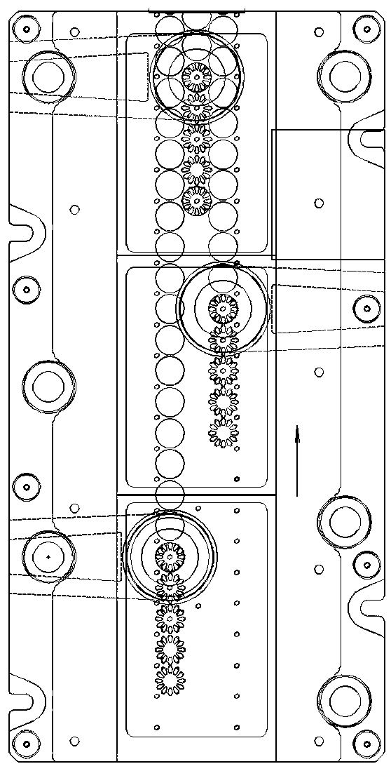
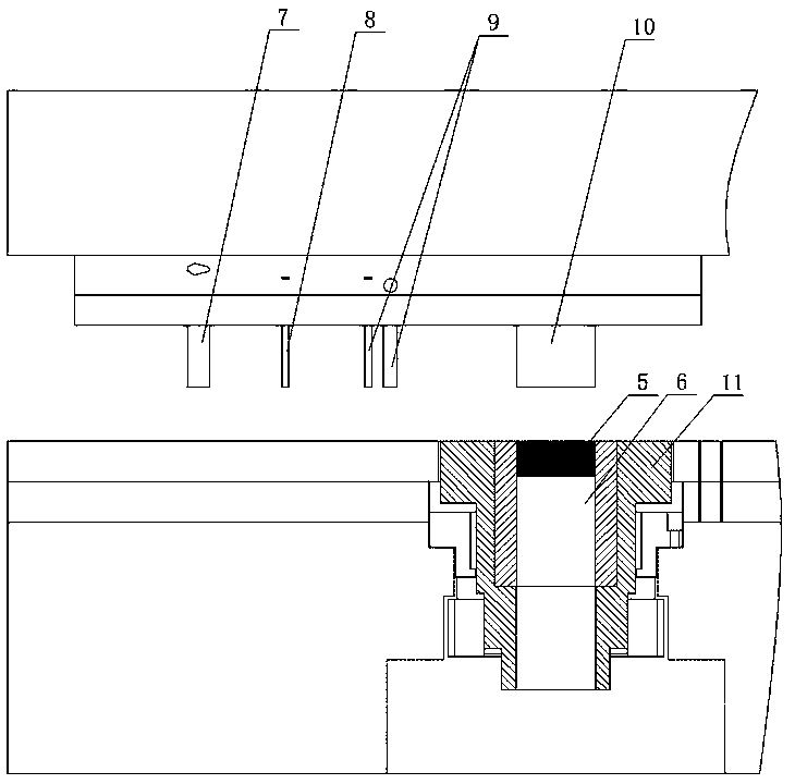
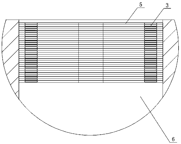
[0016] As shown in the figure, the method for manufacturing the rotor sheet of the present invention includes the following steps: the iron plate for making the rotor sheet is conveyed step by step, and the first, second, third and fourth processes are arranged in sequence on the step-by-step conveying path. The first station is equipped with a first punching head 7 to punch out the blade slot 1 on the iron plate, the second station is equipped with a second punching head 8 to punch out the metering hole 2 on the iron plate, and the third station is set A third stamping head 9 punches out the stacking riveting point 3 and the central axis hole 4 on the iron plate, the stamping position of the stacking riveting point 3 is the same as that of the metering hole 2, and the fourth station is provided with a fourth stamping head 10 to make The rotor sheet 5 is blanked into the blanking cavity 6 and riveted with the previous rotor sheet in the blanking cavity 6 , and the blanking cavi...


PUM


Abstract

The invention discloses a rotor piece manufacturing method. The rotor piece manufacturing method is characterized by comprising the following steps: rotor piece iron plates are conveyed in a steppingmanner; in a stepping conveying path, first, second, third and fourth stations are provided in sequence; a first punch is arranged in the first station for punching blade groove holes in the iron plates; a second punch is arranged in the second station for punching metering holes in the iron plates; a third punch is arranged in the third station for punching overlap riveting points in the iron plates, specifically, the overlap riveting points and the metering holes are the same in punching position; a fourth punch is arranged in the fourth station for blanking rotor pieces into a blanking diecavity for overlap riveting with previous rotor pieces in the blanking die cavity; when the fourth punch carries out punching once, the blanking die cavity is revolved by 90 degrees; and when the second punch carries out punching once, the rest of the punches carry out punching N times, specifically, N is equal to the overlap riveting number of the rotor pieces of rotor iron cores. The rotor piecemanufacturing method can realize full-automatic production of the rotor iron cores to greatly improve the efficiency; meanwhile, produced rotor iron cores are high in dynamic balance stability; and in addition, the invention provides a rotor piece manufacturing mold.

Description

technical field [0001] The invention relates to a motor rotor, in particular to a manufacturing method and a mold for a rotor sheet of the motor rotor. Background technique [0002] The rotor core is an important part of the motor rotor, and the rotor core is composed of multiple rotor pieces stacked and riveted together. In the prior art, the rotor slices of the rotor core are processed by stamping, and then riveted. During the riveting process, the rotor slices must be weighed to ensure that the rotor slices are taken out when they are riveted to a certain amount (rotor core Generally, 20-50 rotor pieces are stacked and riveted), the structure is complex and the work efficiency is low; more importantly, when multiple rotor pieces are stacked and riveted together to form the rotor core, the center shaft hole of the rotor piece is inevitably separated from the There is a concentricity error between the outer circles of the rotor pieces, and at the same time, it is affected ...

Claims


Application Information

Patent Timeline
Patent Type & Authority Applications(China)
IPC IPC(8): B21D28/26B21D39/03B21D37/08H02K15/02H02K15/16
CPCH02K15/02H02K15/165B21D28/26B21D37/08B21D39/031
Inventor 李望章余权波宁广福
Owner 浙江得业电机科技有限公司
Why Eureka
Try Eureka