Supercharge Your Innovation With Domain-Expert AI Agents!

Fixing device of steel bar bending machine

A fixing device and bending machine technology, applied in the field of construction, can solve the problems of lack of safety protection for hydraulic steel bar bending machines, and achieve the effects of compact structure, simple and quick operation, and prevention of injuries

Pending Publication Date: 2018-11-06
NANJING ZHUONAI HEAVY MACHINERY MFG CO LTD
View PDF7 Cites 0 Cited by
  • Summary
  • Abstract
  • Description
  • Claims
  • Application Information

AI Technical Summary

Problems solved by technology

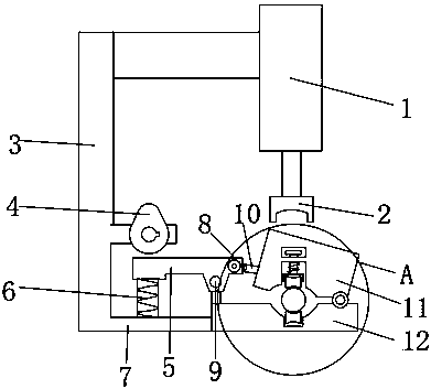
[0003] The purpose of the present invention is to solve the problem of lack of safety protection in the hydraulic steel bar bending machine in the prior art, and propose a fixing device for the steel bar bending machine

Method used


Image

  • Fixing device of steel bar bending machine
  • Fixing device of steel bar bending machine
  • Fixing device of steel bar bending machine

Examples


Embodiment Construction

[0017] The following will clearly and completely describe the technical solutions in the embodiments of the present invention with reference to the accompanying drawings in the embodiments of the present invention. Obviously, the described embodiments are only some, not all, embodiments of the present invention.

[0018] In describing the present invention, it should be understood that the terms "upper", "lower", "front", "rear", "left", "right", "top", "bottom", "inner", " The orientation or positional relationship indicated by "outside", etc. is based on the orientation or positional relationship shown in the drawings, and is only for the convenience of describing the present invention and simplifying the description, rather than indicating or implying that the referred device or element must have a specific orientation, so as to Specific orientation configurations and operations, therefore, are not to be construed as limitations on the invention.

[0019] refer to Figure ...


PUM


Abstract

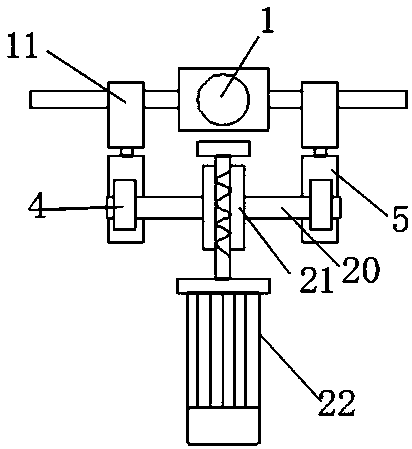
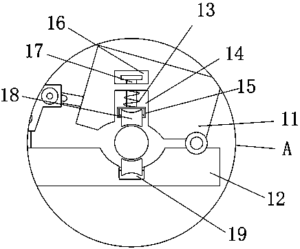
The invention discloses a fixing device of a steel bar bending machine. The fixing device comprises a hydraulic rod, a pressure head is installed at the lower end of the hydraulic rod, the left end ofthe hydraulic rod is connected with a connecting rod, and the connecting rod is horizontally placed; a supporting rod is fixedly connected to the left end of the connecting rod, and a cam is installed on the supporting rod; the lower end of the supporting rod is fixedly connected with a transverse plate, a spring is welded to the upper surface of the transverse plate, and a rotary body is weldedto the upper surface of the spring; the right end of the rotary body is connected with a cylindrical pin, and the cylindrical pin is rotationally connected with a rod body; a sliding groove is formedin the joint of the rod body and the cylindrical pin, and the right end of the rod body is fixedly connected with a first clamping block; and a second clamping block is fixedly connected to the rightend of the transverse plate. The fixing device is compact in structure and easy and fast to use and operate; the two ends of a steel bar are fixed through a clamp, and unnecessary injuries caused by breakage in the bending process of the steel bar can be prevented. The tightness of the clamp is converted through rotation of the cam, and the fixing device is simple and rapid to use.

Description

technical field [0001] The invention relates to the technical field of construction, in particular to a fixing device for a steel bar bending machine. Background technique [0002] On the construction site, the bending of steel bars has been changed from manual bending to mechanical bending. Hydraulic steel bar bending machines are widely used, small in size and easy to operate. However, hydraulic steel bar bending machines on the existing market generally lack safety protection equipment, especially It is the situation that some shorter steel bars are prone to collapse and fly due to excessive force when the steel bars are bent, which is very dangerous for the staff on site. Contents of the invention [0003] The purpose of the present invention is to solve the problem of lack of safety protection in the hydraulic steel bar bending machine in the prior art, and propose a fixing device for the steel bar bending machine. [0004] In order to achieve the above object, the p...

Claims


Application Information

Patent Timeline
IPC IPC(8): B21F1/00
CPCB21F1/004
Inventor 周克谋
Owner NANJING ZHUONAI HEAVY MACHINERY MFG CO LTD
Features
  • R&D
  • Intellectual Property
  • Life Sciences
  • Materials
  • Tech Scout
  • Unparalleled Data Quality
  • Higher Quality Content
  • 60% Fewer Hallucinations
Learn More