Expansion breaking, loading and unloading machine for crank connecting rod

A crank connecting rod and breaking technology, which is applied to chemical instruments and methods, other manufacturing equipment/tools, cleaning methods using gas flow, etc., can solve the problems of manual loading and unloading, and the inability to improve work efficiency, so as to avoid The effect of part confusion

Inactive Publication Date: 2018-11-06
邱丹
View PDF1 Cites 0 Cited by
  • Summary
  • Abstract
  • Description
  • Claims
  • Application Information

AI Technical Summary

Problems solved by technology

This patent fails to solve the problem of manual loading and unloading of the crank connecting rod breaking process, which cannot improve work efficiency

Method used


Image

  • Expansion breaking, loading and unloading machine for crank connecting rod
  • Expansion breaking, loading and unloading machine for crank connecting rod
  • Expansion breaking, loading and unloading machine for crank connecting rod

Examples


Embodiment Construction

[0022] The specific embodiments of the present invention will be described in further detail below in conjunction with the drawings and embodiments of the specification:

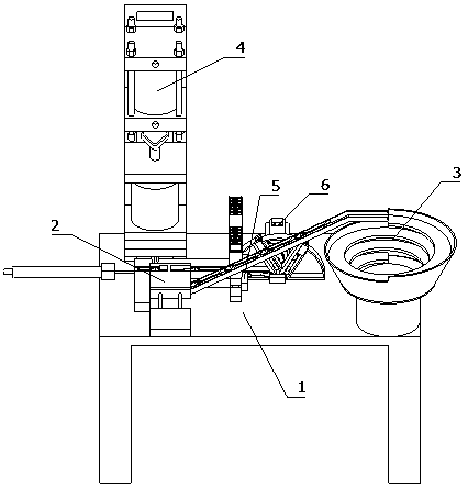
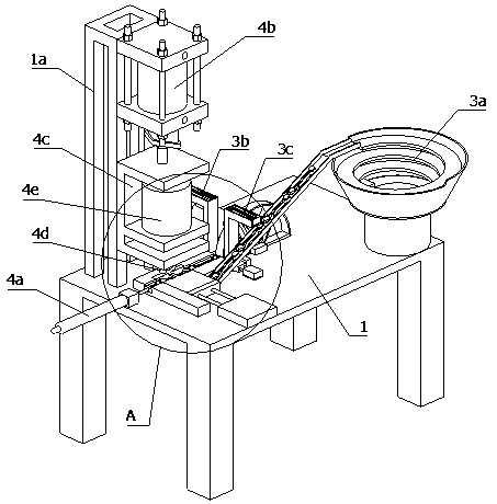
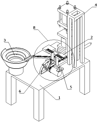
[0023] Reference Figure 1 to Figure 10 The described crank connecting rod expansion and breaking and its loading and unloading machine includes a table 1 and a loading device 3, a breaking device 4, and a discharge device 6 installed on the table 1. The loading device 3 includes: The first feeding device 3a, the second feeding device 3b and the third feeding device 3c. The discharge port of the first feeding device 3a is provided with a processing table 2 which can drive the crankshaft connecting rod to slide on the table 1. The discharge ports of the second feeding device 3b and the third feeding device 3c are provided with an assembly device 5 for assembling the crank connecting rod after expansion, and the processing table 2 is provided with a driving processing table 2 to move to the expansion device 4 on ...


PUM


Abstract

The invention relates to the field of automobile part manufacture, in particular to an expansion breaking, loading and unloading machine for a crank connecting rod. A machining platform capable of driving the crank connecting rod to slide on a table is arranged at a discharge port of a first loading device, and an assembling device used for assembling the crank connecting rod obtained after expansion breaking is arranged at discharge ports of a second loading device and a third loading device; an expansion breaking device comprises a core rod and a vertical moving device used for driving the core rod to do vertical reciprocating motion; the assembling device comprises clamping blocks capable of clamping the two sides of the large-shaft end of the crank connecting rod obtained after expansion breaking and a limiting device used for limiting the crank connecting rod obtained after expansion breaking from moving; and third horizontal moving devices used for driving the clamping blocks tooppositely move and clamping the two sides of the large-shaft end of the crank connecting rod obtained after expansion breaking are arranged on the two sides of the limiting device. According to the device, continuous expansion breaking machining and automatic loading and unloading can be conducted on the crank connecting rod, the cover ends and the rod ends of the same group of crank connecting rods can be assembled together after machining is completed, and the condition that parts are mixed is avoided.

Description

Technical field [0001] The invention relates to the field of automobile parts manufacturing, in particular to the expansion and breaking of a crank connecting rod and its loading and unloading machine. Background technique [0002] The crank connecting rod has a complicated shape, easy deformation, poor rigidity, and high requirements for dimensional accuracy, position accuracy, and surface quality, which makes it difficult to manufacture. The quality of its connecting rod manufacturing technology directly affects the use performance and economic performance of the connecting rod and the survival and development of an enterprise. With the development of production technology, traditional manufacturing technology gradually cannot meet the requirements of current production. Many connecting rod manufacturers abroad have successively proposed "expansion break technology". The application of the connecting rod expansion process has caused significant changes in the processing quality...

Claims


Application Information

Patent Timeline
Patent Type & Authority Applications(China)
IPC IPC(8): B23P23/00B23P17/02B23P19/00B08B5/02
CPCB23P23/00B08B5/02B23P17/02B23P19/00B23P19/001
Inventor 邱丹
Owner 邱丹
Why Eureka
Try Eureka