Automobile spare tire storage mechanism

A technology for spare tires and automobiles, which is applied to the arrangement of spare tires, vehicle components, transportation and packaging, etc. It can solve the problems of inconvenient disassembly and installation, personnel injuries, etc., and achieve the effect of avoiding easy injuries

Inactive Publication Date: 2018-11-06
ANHUI POLYTECHNIC UNIV
View PDF7 Cites 1 Cited by
  • Summary
  • Abstract
  • Description
  • Claims
  • Application Information

AI Technical Summary

Problems solved by technology

[0003] The current spare tire of a truck is hoisted at the lower end of the frame by means of an iron chain. During installation, the shaft with the ratchet is rotated forcefully by a person, the iron chain is rolled up, and it is lifted to the fastening position at the lower end of the frame, and then locked through the connecting plate. , when it is disassembled for standby installation, it needs to be disassembled artificially. It requires people to drill to the lower end of the frame and bend over to apply force, which is easy to cause injuries, and it is inconvenient to disassemble and install.

Method used


Image

  • Automobile spare tire storage mechanism
  • Automobile spare tire storage mechanism
  • Automobile spare tire storage mechanism

Examples


Embodiment 1

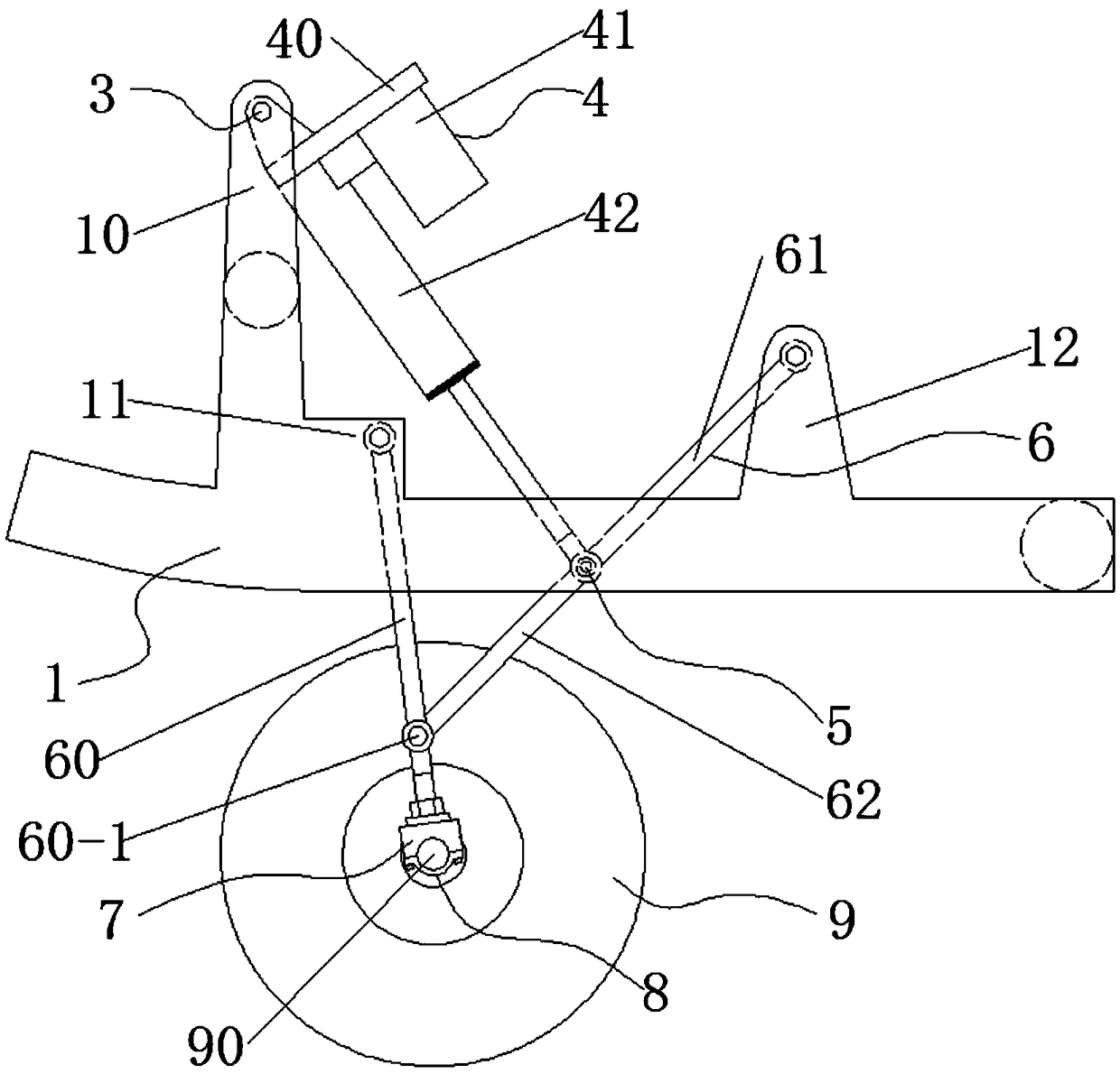
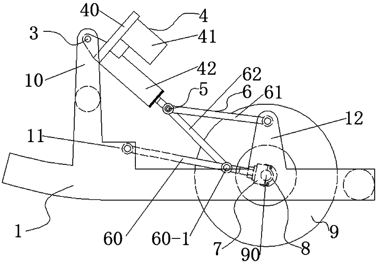
[0023] In this car spare tire storage mechanism, when the car spare tire needs to be folded and stored, the wheel hub 9 is rolled between the two side frame plates 1, and then the hub shaft 90 is placed in the middle of the half shaft seat 7, and then the half shaft cover 8 Tighten the bolts on the half shaft seat 7 to lock the hub shaft 90 firmly, then start the miniature electric push rod 4, the push rod motor 41 drives the electric push rod 42 to shrink, and the first connecting rod 61 and the second connecting rod 62 start from the collinear The state is that the hinge point at the end of the electric push rod 42 is the apex and is folded into an acute angle. During this process, the connecting rod one 61 rotates clockwise around the third hinge part 12. During the folding process of the connecting rod two 62, the connecting rod two 62 By being hinged with the hinge hole 60-1, the support rod 60 is pulled to rotate counterclockwise around the second hinge part 11, and then ...

Embodiment 2

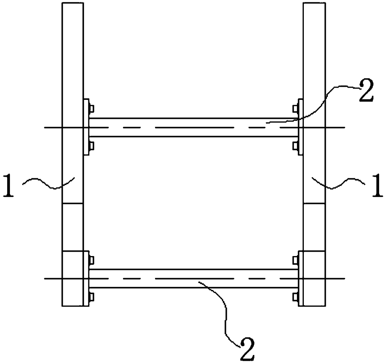
[0026] The connecting rod group 6 is provided with two groups, and they are respectively located inside the side frame plate 1, which ensures the stability of the folding storage and automatic unfolding action; It is circular, which facilitates the installation and locking of the half shaft seat 7.


PUM


Abstract

The invention discloses an automobile spare tire storage mechanism which comprises side frame boards, cross brace stops, a first connecting shaft, a miniature electric push rod, a second connecting shaft, connecting rod sets, axle shaft seats, axle shaft glands and a hub. The two side frame boards are arranged and connected with the ends of the cross brace stops. Each side frame board is providedwith a first hinging part, a second hinging part and a third hinging part. The two ends of the first connecting shaft are connected with the first hinging parts. The miniature electric push rod is composed of a base, a push rod motor and an electric push rod. The base is hinged to the middle portion of the first connecting shaft. The push rod motor and the electric push rod are connected with thebase. The push rod motor drives the electric push rod to stretch out or retract back. The middle of the second connecting shaft is hinged to the end of the electric push rod. Each connecting rod set is composed of a supporting rod, a first connecting rod and a second connecting rod. The axle shaft seats are connected with the ends of the supporting rods. The axle shaft glands are screwed to the axle shaft seats through bolts. Folding storage and automatic unfolding detachment of an automobile spare tire are achieved, and the defect that a person is likely to get hurt in the traditional manuallifting and detaching process is avoided.

Description

technical field [0001] The invention belongs to the technical field of automobile spare tires, in particular, the invention relates to a storage mechanism for automobile spare tires. Background technique [0002] A spare tire is to prepare a spare tire for the car. Once a tire blows out or something goes wrong, the spare tire can be replaced in a convenient and timely manner, so that the car will not break down midway. [0003] The current spare tire of a truck is hoisted at the lower end of the frame by means of an iron chain. During installation, the shaft with the ratchet is rotated forcefully by a person, the iron chain is rolled up, and it is lifted to the fastening position at the lower end of the frame, and then locked through the connecting plate. , When it is disassembled for standby installation, manual disassembly is required. People need to drill to the lower end of the frame and bend down to apply force, which is easy to cause injury to personnel, and it is inco...

Claims


Application Information

Patent Timeline
Patent Type & Authority Applications(China)
IPC IPC(8): B62D43/00B62D43/02
CPCB62D43/002B62D43/02
Inventor 李仁军漆小敏王静平王健博吕涛奚威陶玮李雪婷卢鸿
Owner ANHUI POLYTECHNIC UNIV
Why Eureka
Try Eureka