Interlaced Laying System and Application Method of Honeycomb Porous Structure Cotton

A porous structure, staggered technology, used in textiles, papermaking, non-woven fabrics, etc., can solve the problems of inability to form staggered multi-layer textiles, single laying direction, etc., and achieve the effect of rich laying directions

Active Publication Date: 2019-09-03
平邑经济开发区投资发展有限公司
View PDF6 Cites 0 Cited by
  • Summary
  • Abstract
  • Description
  • Claims
  • Application Information

AI Technical Summary

Problems solved by technology

[0005] The purpose of the present invention is to overcome the defects and problems existing in the prior art that the stacking direction is single and cannot form an interlaced multi-layer textile body, and provide a honeycomb porous structure with rich stacking directions and the ability to form an interlaced multi-layer textile body Cotton staggered laying system and method of use

Method used


Image

  • Interlaced Laying System and Application Method of Honeycomb Porous Structure Cotton
  • Interlaced Laying System and Application Method of Honeycomb Porous Structure Cotton
  • Interlaced Laying System and Application Method of Honeycomb Porous Structure Cotton

Examples


Embodiment 1

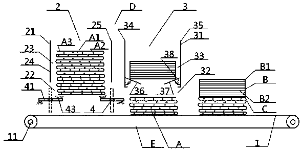
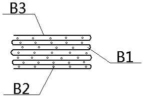
[0052] see Figure 1 to Figure 6 , a kind of staggered laying system of honeycomb porous structure cotton, comprising a laying unit D and a transmission unit E, the transmission unit E includes a conveyor belt 1 and a driving roller 11, the two ends of the conveyor belt 1 are respectively connected to the outer circumference of the driving roller 11 Connected, a laying unit D is arranged directly above the middle of the conveyor belt 1; the laying unit D includes a left and right laying device 2 and a front and rear laying device 3 arranged side by side along the conveyor belt 1, and the left and right laying device 2 includes The left and right guides 21 and the left and right cotton outlets 22 arranged directly below, the front and rear laying device 3 includes the front and rear guides 31 and the front and rear cotton outlets 32 arranged directly below, the left and right guides 21, front and rear guides 31 are all hollow structures. The left and right inner cavities 23 pro...

Embodiment 2

[0055] Basic content is the same as embodiment 1, the difference is:

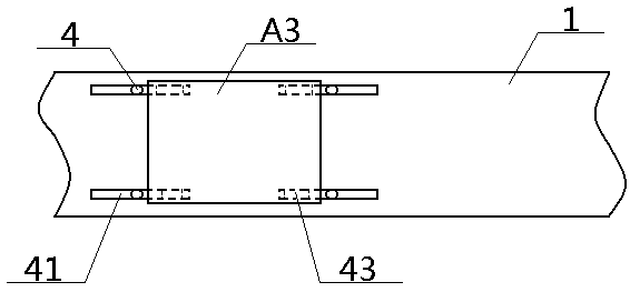
[0056] The left and right cotton output areas 22 are provided with four weight-limiting cotton output structures 4 with the same structure. A single weight-limiting cotton output structure 4 includes horizontal weight-limiting tubes 41 and vertical rotating tubes 42, both of which are hollow structures. The horizontal weight-limiting tubes The top of one end of 41 is provided with positive air outlet 43, and the bottom of the other end of horizontal weight-limiting tube 41 is provided with anti-air outlet 44, and the middle position of horizontal weight-limiting tube 41 is vertically connected with the inner end of vertical rotation tube 42, and vertical rotation The outer end of pipe 42 is connected with rotating bearing 45, and the inner cavity of horizontal weight-limiting pipe 41, positive air outlet 43, reverse air outlet 44, and vertical rotating pipe 42 are all connected to each other; four weight-lim...

Embodiment 3

[0059] Basic content is the same as embodiment 1, the difference is:

[0060] The left and right sides of described front and rear inner cavity 33 are respectively provided with mutually parallel front and rear left cavity plate 34, front and rear right cavity plate 35, and the inner surfaces of front and back left cavity plate 34, front and rear right cavity plate 35 are respectively connected with the left limit weight springboard. 36. The inner ends of the right weight-limiting springboard 37 are fixedly connected, and the outer ends of the left weight-limiting springboard 36 and the right weight-limiting springboard 37 extend downward in the direction of the central axis of the front and rear inner cavity 33. The outer ends of the heavy rebounding plate 36 and the right limiting weight rebounding plate 37 are lower than the corresponding inner ends respectively, the distance between the outer end of the left limiting heavy rebounding plate 36 and the outer end of the right ...


PUM


Abstract

The invention relates to an interlaced laying and folding system of honeycomb porous structure cotton. The system comprises a conveying unit and a laying and folding unit disposed on the conveying unit, the laying and folding unit comprises a left-right laying and folding device and a front-rear laying and folding device which are arranged side by side, the left-right laying and folding device comprises a left-right inner cavity and a left-right cotton discharging area which are vertically communicated with each other, and the front-rear laying and folding device comprises a front-rear inner cavity and a front-rear cotton discharging area which are vertically communicated with each other; the right side of the left-right cotton discharging area and the left side of the front-rear cotton discharging area are communicated with each other in a transport direction, and the left-right laying and folding device and the front-rear laying and folding device are internally provided with automatic ascending structures of laying and folding bodies respectively. According to the design, not only can interlaced arrangement between nets, between the nets and filaments and between the filaments be achieved at the same time, but also laying folding directions can be diversified, interlaced multi-layer textile bodies can be formed, and the overall system is high in firmness, easy to operate andgreat in adjustability.

Description

technical field [0001] The invention relates to a fiber web laying device, which belongs to the field of textile machinery, in particular to a staggered laying system of honeycomb porous structure cotton and its use method, which is particularly suitable for enriching laying directions and forming staggered multi-layers textile body. Background technique [0002] At present, in the textile field, the processing method of laying the carded fiber web into a multi-layer textile body according to the requirements is called web laying, which is mainly completed by web laying machines. The existing web laying machines include horizontal web laying machines There are two kinds of vertical lappers. [0003] The fibers in the products processed by the horizontal lapper are arranged in the horizontal direction, and the elasticity is poor. The fibers in the products processed by the vertical lapper are arranged in the vertical direction, and the elasticity is strong, but whether it is...

Claims


Application Information

Patent Timeline
IPC IPC(8): D04H5/10D04H5/06
Inventor 张智明段耀帅卢宾宾徐巧梅顺齐姬巧玲肖人彬
Owner 平邑经济开发区投资发展有限公司
Why Eureka
Try Eureka