Indoor drying rack

A technology for clothes drying racks and clothes, which is applied in the field of indoor clothes drying racks, and can solve problems such as non-adjustable relative positions and inconvenient use

Inactive Publication Date: 2018-11-06
太仓柏嘉装饰工程有限公司
View PDF6 Cites 0 Cited by
  • Summary
  • Abstract
  • Description
  • Claims
  • Application Information

AI Technical Summary

Problems solved by technology

[0002] The clothes-drying pole or the hook of the existing clothes-drying rack are all fixedly installed on the wall, and its relative position with the wall cannot be adjusted, which brings inconvenience to the use

Method used


Image

  • Indoor drying rack

Examples


Embodiment Construction

[0010] The specific implementation manners of the present invention will be further described below in conjunction with the drawings and examples. The following examples are only used to illustrate the technical solution of the present invention more clearly, but not to limit the protection scope of the present invention.

[0011] The technical scheme of concrete implementation of the present invention is:

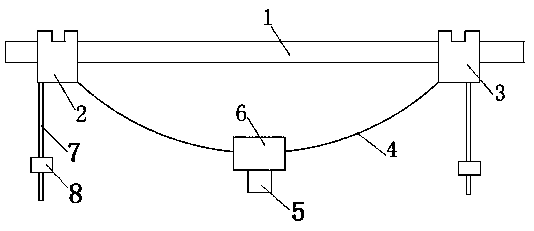
[0012] Such as figure 1 as shown,

[0013] An indoor clothes hanger, comprising a horizontal sliding rod 1 arranged on the wall, the sliding rod 1 is covered with a first sliding sleeve 2 and a second sliding sleeve 3, and the first sliding sleeve 2 and the second sliding sleeve 3 are respectively connected with The sliding rod 1 is slidably matched, the first sliding sleeve 2 and the second sliding sleeve 3 are connected through the installation chain 4, the middle part of the installation chain 4 is suspended with an installation block 6, and the installation block 6 i...


PUM


Abstract

The invention discloses an indoor drying rack. The hanging frame comprises a sliding rod parallel arranged on a wall, the sliding rod is sleeved with a first sliding sleeve and a second sliding sleeve, the first and second sliding sleeves are slidably matched with the sliding rod, the first and second sliding sleeves are connected through an installing chain, installing blocks are suspended in themiddle of the installing chain, hooks used for hanging clothes are arranged on the installing blocks, rope strips are connected with the first and second sliding sleeves, and fastening rings used formatching with the rope strips are arranged on the wall. The drying rack has the advantages that the height positions, relative to the wall, of the hooks used for hanging clothes are adjustable.

Description

technical field [0001] The invention relates to the technical field of interior decoration, in particular to an indoor clothes drying rack. Background technique [0002] The clothes-drying rod or the hook of the existing clothes-drying rack are all fixedly installed on the wall, and its relative position with the wall cannot be adjusted, which brings inconvenience to use. Contents of the invention [0003] The object of the present invention is to provide an indoor clothes drying rack, the height of the hook used for hanging clothes can be adjusted relative to the position of the wall. [0004] To achieve the above object, the present invention provides the following technical solutions: [0005] An indoor clothes hanger, comprising a horizontal sliding bar arranged on the wall, the sliding bar is covered with a first sliding sleeve and a second sliding sleeve, and the first sliding sleeve and the second sliding sleeve respectively slide and cooperate with the sliding bar...

Claims


Application Information

Patent Timeline
Patent Type & Authority Applications(China)
IPC IPC(8): D06F57/12
CPCD06F57/12
Inventor 陆叶
Owner 太仓柏嘉装饰工程有限公司
Why Eureka
Try Eureka