Steel structure column convenient to adjust

A steel structure and support column technology, applied in the field of steel structure columns, can solve the problems of increasing workload, reducing the stability of steel structure columns, complex installation structures, etc., and achieve the effect of avoiding splicing intervals, increasing the use range, and simple installation structures

Inactive Publication Date: 2018-11-06
句容市春诚工艺丝毯厂
View PDF1 Cites 2 Cited by
  • Summary
  • Abstract
  • Description
  • Claims
  • Application Information

AI Technical Summary

Problems solved by technology

[0003] The height of the steel structure column is generally fixed and cannot be adjusted. During the construction and splicing process, the steel structure column is prone to be too high or too low, resulting in gaps in the splicing, making the splicing work impossible or increasing the difficulty of splicing. As a result, it is difficult to complete the construction of the building frame, which increases the difficulty of work and reduces work efficiency; the steel structure column is vulnerable to a certain impact during construction or transportation. When the impact force is too large, it is easy to cause deformation of the steel structure column and reduce the steel structure. The stability of the column makes the steel structure column a potential safety hazard and threatens the safety of the staff. A Chinese patent discloses an anti-blast energy-consuming steel structure column (authorized announcement number CN207296180U). This patented technology can effectively strengthen the longitudinal Compressive strength, however, cannot increase the transverse compressive strength; when steel structural columns are built with steel beams and other structures, multiple fixing bolt assemblies are used, the installation structure is complicated, the workload is increased, and the work efficiency is reduced

Method used


Image

  • Steel structure column convenient to adjust
  • Steel structure column convenient to adjust

Examples


Embodiment Construction

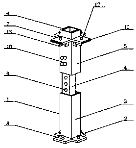
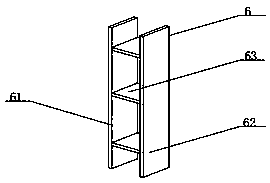
[0017] see Figure 1~2 , in an embodiment of the present invention, a steel structure column that is easy to adjust includes a steel structure column body 1, a base 2 is provided at the bottom of the steel structure column body 1, and a first support column 3 is fixedly installed on the upper surface of the base 2 , the top of the first support column 3 is fixedly installed with the second support column 4, the outside of the second support column 4 is installed with the third support column 5, the upper surface of the base 2 is evenly opened with the first installation hole 8, the first The number of mounting holes 8 is four, and the inside of the first mounting hole 8 is fixedly installed with fixing bolts, the number of the second limiting holes 10 is two, and the second limiting holes 10 are distributed in parallel in the vertical direction, The inside of the second limit hole 10 is fixedly equipped with limit bolts. By setting the second support column 4 and the third sup...


PUM


Abstract

The invention discloses a steel structure column convenient to adjust. The steel structure column comprises a steel structure column body; a base is arranged at the bottom of the steel structure column body; a first supporting column is fixedly mounted on the upper surface of the base; a second supporting column is fixedly mounted at the top end of the first supporting column; a third supporting column is movably mounted outside the second supporting column; a reinforcing device is fixedly mounted on the inner wall of the third supporting column; and installation plates are fixedly mounted outside the third supporting column. Through arrangement of the second supporting column and the third supporting column, height of the steel structure column can be conveniently adjusted; the second supporting column is fixed through first limiting holes, second limiting holes and limiting bolts, application range of the steel structure column body is enlarged, splicing intervals are avoided, splicing difficulty is reduced, normal splicing work is guaranteed, working efficiency is improved; and through arrangement of the reinforcing device, anti-pressure capacity of the steel structure column body is improved.

Description

technical field [0001] The invention relates to the technical field of steel structure columns, in particular to an adjustable steel structure column. Background technique [0002] Steel structural column is a column made of steel. At present, the supporting columns of large and medium-sized industrial plants, large-span public buildings, high-rise buildings, light mobile houses, working platforms, trestles and brackets are mostly steel structural columns. [0003] The height of the steel structure column is generally fixed and cannot be adjusted. During the construction and splicing process, the steel structure column is prone to be too high or too low, resulting in gaps in the splicing, making the splicing work impossible or increasing the difficulty of splicing. As a result, it is difficult to complete the construction of the building frame, which increases the difficulty of work and reduces work efficiency; the steel structure column is vulnerable to a certain impact dur...

Claims


Application Information

Patent Timeline
Patent Type & Authority Applications(China)
IPC IPC(8): E04C3/32
CPCE04C3/32
Inventor 张牛扣
Owner 句容市春诚工艺丝毯厂
Why Eureka
Try Eureka