
Power adjusting range based head-swinging ceiling fan for dormitory

A width and dormitory technology, applied in the field of living utensils, can solve the problems that the side beds cannot be blown to the wind, the fan has insufficient wind width, etc., and achieve the effect of stable support and increased blowing area

Active Publication Date: 2018-11-06
诸暨叶蔓电子商务有限公司
View PDF6 Cites 0 Cited by
  • Summary
  • Abstract
  • Description
  • Claims
  • Application Information

AI Technical Summary

Problems solved by technology

[0005] Aiming at the deficiencies of the prior art, the present invention provides a dormitory swing-head ceiling fan based on power-adjustable format, which solves the problem that the existing dormitory fans have insufficient air output and the side beds cannot be blown by the wind.

Method used

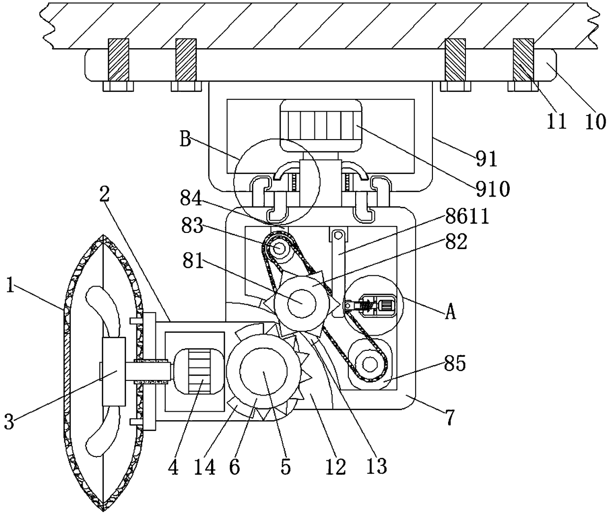

Image

  • Power adjusting range based head-swinging ceiling fan for dormitory
  • Power adjusting range based head-swinging ceiling fan for dormitory
  • Power adjusting range based head-swinging ceiling fan for dormitory

Examples


Embodiment 1

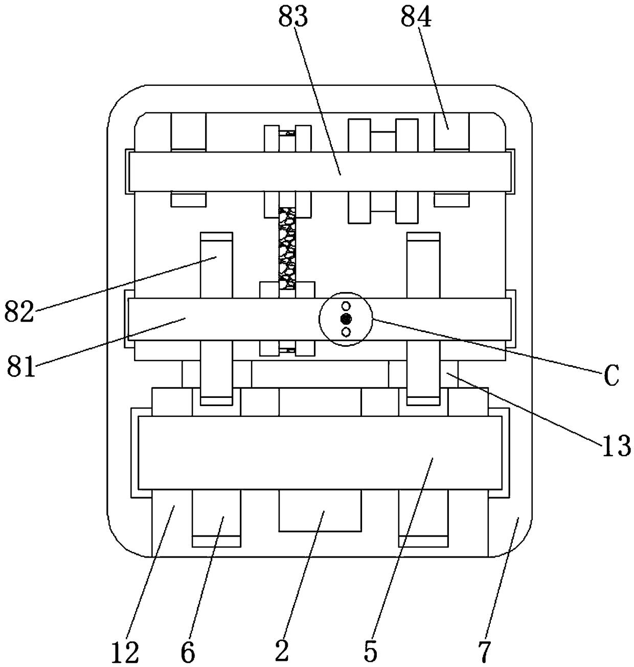
[0033] Such as Figure 1-5As shown, a dormitory swing-head ceiling fan based on power adjustment format includes a fan cover 1, a transmission column 2 is arranged on one side of the fan cover 1, fan blades 3 are provided in the inner cavity of the fan cover 1, and the inside of the transmission column 2 The first motor 4 is fixedly connected, the end of the transmission column 2 away from the fan cover 1 is fixedly connected with the transmission shaft 5, the two ends of the transmission shaft 5 are symmetrically fixedly connected with the first gear 6, and one end of the transmission column 2 is provided with a rotation column 7, The inner cavity of the rotating column 7 is provided with a drive mechanism 8, the top of the rotating column 7 is provided with an amplifying mechanism 9, the top of the amplifying mechanism 9 is provided with a fixed plate 10, and both sides of the fixed plate 10 bottom are symmetrically provided with bolts 11, and the rotating column 7 The botto...

Embodiment 2

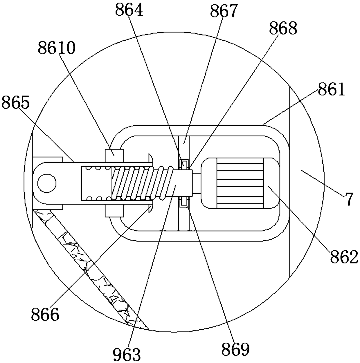
[0035] On the basis of Embodiment 1, the fixing mechanism 86 includes a pressure-bearing box 861, and a third motor 862 is fixedly connected to the middle of one side of the inner wall of the pressure-bearing box 861. shaft, the end of the output shaft of the third motor 862 is fixedly connected with a threaded rod 863, the top and bottom of the threaded rod 863 are symmetrically fixedly connected with a slider 864 on the side close to the third motor 862, and the other end of the threaded rod 863 is provided with a threaded sleeve 865 The top and bottom of the threaded sleeve 865 are symmetrically fixedly connected with a block 866 on one side close to the threaded rod 863, and a threaded groove is opened in the middle of one side of the threaded sleeve 865.

Embodiment 3

[0037] On the basis of Embodiments 1 and 2, the middle part of the inner cavity of the pressure box 861 is fixedly connected to the limiting plate 867, the middle part of the limiting plate 867 is provided with a through hole 868 passing through it, and the four sides of the inner wall of the through hole 868 are provided with annular The chute 869, the center of the other side of the pressure box 861 is provided with a first opening, the first opening is fixedly connected with a limit block 8610, the other end of the threaded rod 863 is rotatably connected with a moving rod 8611, and the moving rod 8611 is away from the threaded rod 863 A fixed block 8612 is fixedly connected to the bottom of one side.


PUM


Abstract

The invention discloses a power adjusting range based head-swinging ceiling fan for a dormitory, and relates to the technical field of utensils of life. The power adjusting range based head-swinging ceiling fan for the dormitory comprises a fan cover, wherein a transmission column is arranged at one side of the fan cover; blades are arranged in an inner cavity of the fan cover; a first motor is fixedly connected into the transmission column a transmission shaft is fixedly connected to one end, far away from the fan cover, of the transmission column; first gears are symmetrically fixedly connected to two ends of the transmission shaft; a rotating column is arranged at one end of the transmission column; a driving mechanism is arranged in an inner cavity of the rotating column; a range expanding mechanism is arranged on the top part of the rotating column; and a fixed plate is arranged on the top part of the range expanding mechanism. According to the power adjusting range based head-swinging ceiling fan for the dormitory, the air outlet range of the fan for the dormitory is extremely expanded, and moreover, the working stability is ensured; and the practicability is improved while the problems that the air outlet range of an existing fan for the dormitory is narrow and air cannot be blown to beds at side are solved.

Description

technical field [0001] The invention relates to the technical field of living appliances, in particular to an oscillating ceiling fan for a dormitory based on a power-adjustable format. Background technique [0002] Whenever summer comes, the weather is hot. Even if there are fans in the school dormitory, because the fan blowing range is small, not every location can enjoy the fan. In order to increase the blowing area, it is necessary to install multiple fans to Increase the blowing area, which wastes space and energy. [0003] For this reason, Chinese Patent No. CN107906035A proposes a ceiling-absorbing electric fan for dormitories, which uses the design of an air guide cover, which can guide the wind generated by the fan to blow out from both sides, improving the utilization rate of wind energy, and this new type of ceiling-absorbing fan for dormitories The blowing angle of the top electric fan can be adjusted, which can solve the problem of no wind blowing on the upper ...

Claims


Application Information

Patent Timeline
IPC IPC(8): F04D25/10
CPCF04D25/088F04D25/105
Inventor 田粒波
Owner 诸暨叶蔓电子商务有限公司
Learn More