Garbage pyrolysis gasification and secondary combustion chamber integrated device

A technology of pyrolysis gasification and secondary combustion chamber, which is applied in the direction of incinerator, combustion method, combustion type, etc., can solve the problems of dust-proof baffles affecting the observation line of sight, affecting the observation line of sight, and the small range of fire observation, so as to achieve saving Energy, faster disposal, and floor space savings

Active Publication Date: 2018-11-06
江苏金煌环境工程有限公司
View PDF12 Cites 5 Cited by
  • Summary
  • Abstract
  • Description
  • Claims
  • Application Information

AI Technical Summary

Problems solved by technology

Disadvantages: (1) The dust-proof baffle affects the observation line of sight
The anti-dust baffle is generally installed in the center of the fire viewing tube, which affects the observation line of sight
(2) Without heat insulation measures, it is easy to cause safety accidents
The fire viewing tube is directly inserted into the furnace, usually made of metal material, which conducts heat quickly, which will cause the entire fire viewing device to form a high temperature, which is likely to cause burns and safety accidents during observation and replacement of glass.
(3) Viewing angle of fire is narrow
The fire viewing tube is a straight tube structure, which makes the fire viewing angle narrow and the fire viewing range small

Method used


Image

  • Garbage pyrolysis gasification and secondary combustion chamber integrated device
  • Garbage pyrolysis gasification and secondary combustion chamber integrated device
  • Garbage pyrolysis gasification and secondary combustion chamber integrated device

Examples


Embodiment Construction

[0028] The present invention will be described in further detail below in conjunction with the accompanying drawings.

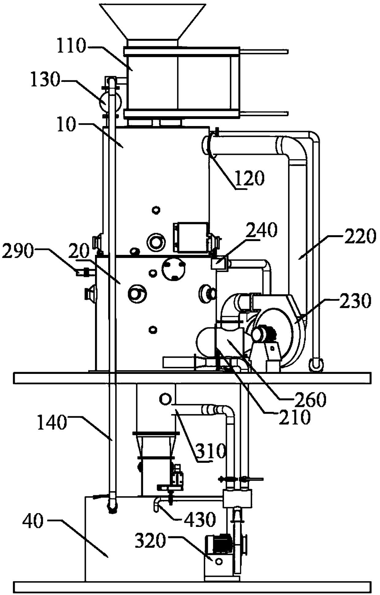
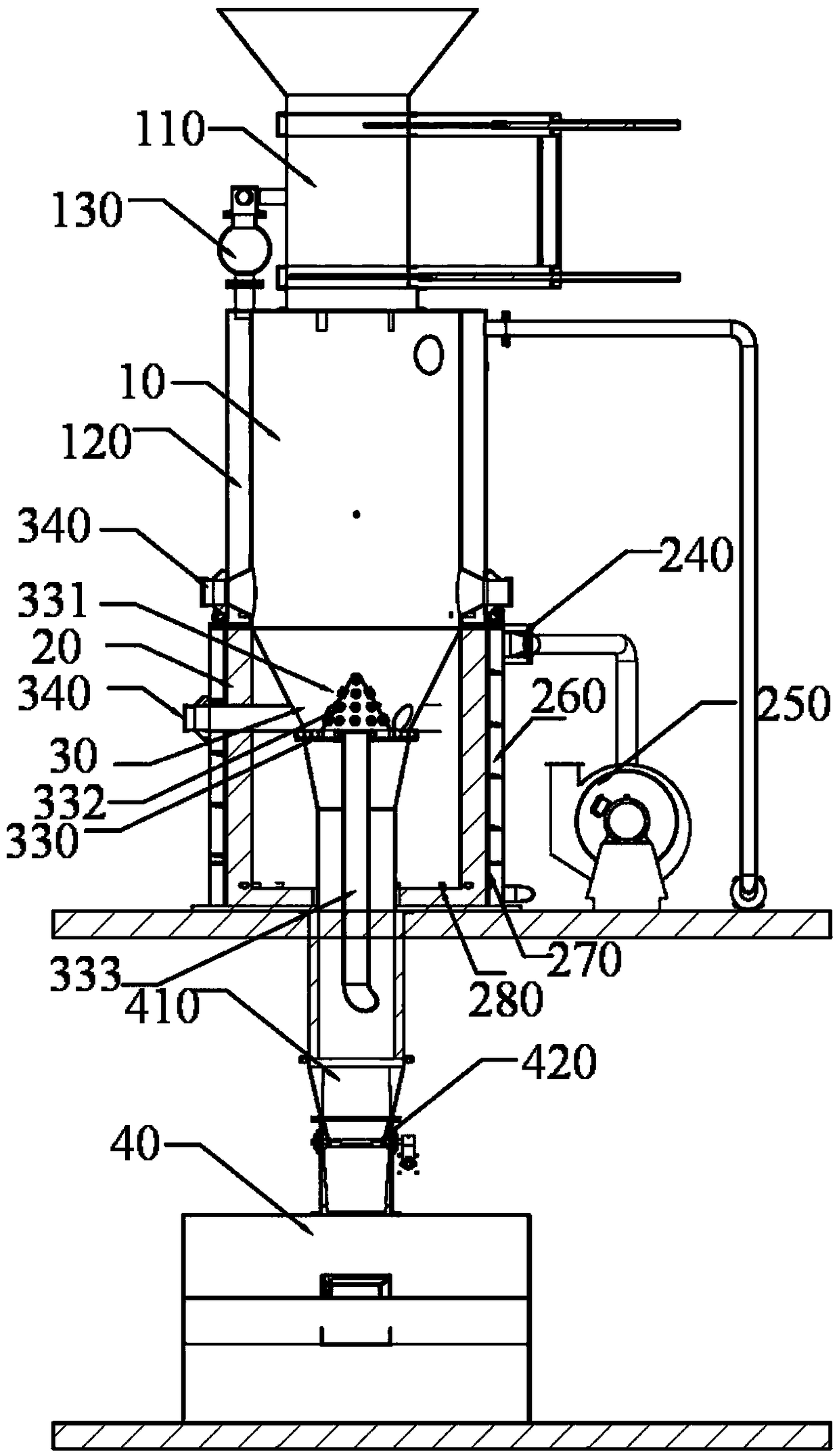
[0029] like figure 1 and 2 as shown,

[0030] A waste pyrolysis gasification and secondary combustion chamber integrated device, comprising:

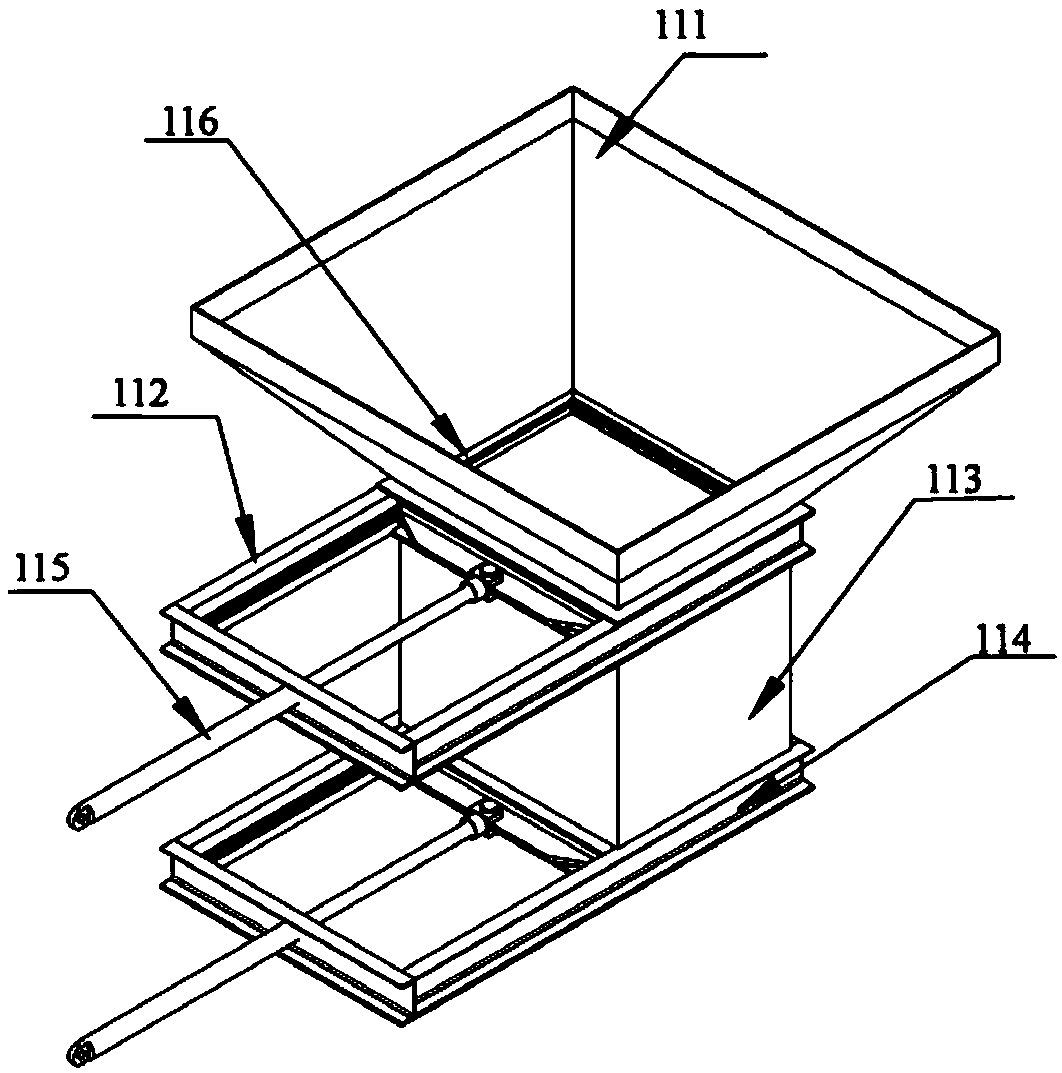
[0031] A gasification furnace 10, the top of the gasification furnace 10 is provided with a feeding device 110, and the side wall of the gasification furnace 10 is provided with a flue gas outlet 120;

[0032] The second combustion chamber 20, the second combustion chamber 20 is arranged under the gasification furnace 10 and is fixedly connected with the gasification furnace 10, the side wall of the second combustion chamber 20 is provided with a flue gas inlet 210, and the flue gas inlet 210 and the flue gas outlet 120 pass through the flue 220 is connected, and the flue 220 is provided with a first fan 230 and a combustion furnace 260;

[0033] Conical cylinder 30, which is arranged in the second combustion chamb...


PUM


Abstract

The invention discloses a garbage pyrolysis gasification and secondary combustion chamber integrated device. The garbage pyrolysis gasification and secondary combustion chamber integrated device comprises a gasification furnace, a secondary combustion chamber, a conical barrel and a slag box. A feeding device is arranged on the top of the gasification furnace, and a smoke outlet is formed in the side wall of the gasification furnace. The secondary combustion chamber is arranged below the gasification furnace and fixedly connected with the gasification furnace. A smoke inlet is formed in the side wall of the secondary combustion chamber, the smoke inlet communicates with the smoke outlet through a flue, and the flue is provided with a first draught fan and a spraying combustion furnace. Theconical barrel is arranged in the secondary combustion chamber and communicates with the gasification furnace. The slag box communicates with the conical barrel through a slag falling pipeline, and the slag falling pipeline is provided with a flap valve. According to the main characteristics of the device, the gasification furnace and the secondary combustion chamber are integrated, the problem that continuous and stable gas generation cannot be achieved during garbage gasification is solved, accordingly, garbage incineration pyrolysis gasification is relatively stable, the garbage treatmentspeed is increased, it is guaranteed that the secondary combustion chamber conducts continuous incineration and fire is not stopped, the temperature is guaranteed, the garbage hot burning reduction rate and the slag amount are reduced, energy is saved, and the occupied area is saved.

Description

technical field [0001] The invention relates to the technical field of garbage treatment, in particular to an integrated device of garbage pyrolysis gasification and a second combustion chamber. Background technique [0002] With the rapid development of my country's social economy, the acceleration of urbanization and the rapid improvement of people's living standards, the amount of urban domestic waste is also increasing. The living environment has caused continuous pollution, which in turn poses a threat to human health. The problem of municipal solid waste has attracted more and more attention. The pyrolysis gasifier is a professional equipment designed and developed for the treatment of solid waste. [0003] The pyrolysis gasification furnaces commonly used today are relatively independent, that is, the pyrolysis gasification furnace burns and gasifies the garbage, and the combustible gas generated is burned in the secondary combustion chamber, but there are some common ...

Claims


Application Information

Patent Timeline
Patent Type & Authority Applications(China)
IPC IPC(8): F23G5/027F23G5/16F23G5/44
CPCF23G5/027F23G5/165F23G5/44
Inventor 李智孙强林
Owner 江苏金煌环境工程有限公司
Why Eureka
Try Eureka