Display substrate, display panel, touch display device and manufacturing method thereof

A touch display device and display panel technology, applied in the fields of touch display devices, display panels, and display substrates, can solve the problems of complicated binding process of plug-in touch display devices, reduce binding steps, and simplify binding The effect of the process

Active Publication Date: 2018-11-06
BOE TECH GRP CO LTD +1
View PDF5 Cites 58 Cited by
  • Summary
  • Abstract
  • Description
  • Claims
  • Application Information

AI Technical Summary

Benefits of technology

This technology allows for direct attachment between an electronic device (such as a computer) screen or other surface without having any extra components attached thereto like wires or connectors. By adding another part called a special pad onto this area instead of just connecting two parts together, there will no longer have these connections needed. Additionally, by integrating both the touch and drive functions into one component, fewer steps may also be required during assembly compared to traditional methods such as attaching separate devices afterwards.

Problems solved by technology

This patented technology involves attaching an electronic component called Touch Panel onto one side of a Display Plane by way of bonds between two films made from different materials like Polyimide tape and Laminate Sheet. These connections require complex processes during manufacturing.

Method used


Image

  • Display substrate, display panel, touch display device and manufacturing method thereof
  • Display substrate, display panel, touch display device and manufacturing method thereof
  • Display substrate, display panel, touch display device and manufacturing method thereof

Examples


Embodiment Construction

[0047] In order to make the purpose, technical solutions and advantages of the embodiments of the present invention more clear, the following will clearly and completely describe the technical solutions of the embodiments of the present invention in conjunction with the drawings of the embodiments of the present invention. Apparently, the described embodiments are some, not all, embodiments of the present invention. All other embodiments obtained by those skilled in the art based on the described embodiments of the present invention belong to the protection scope of the present invention.

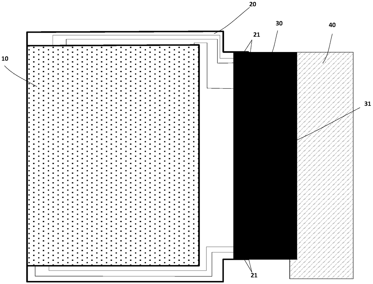
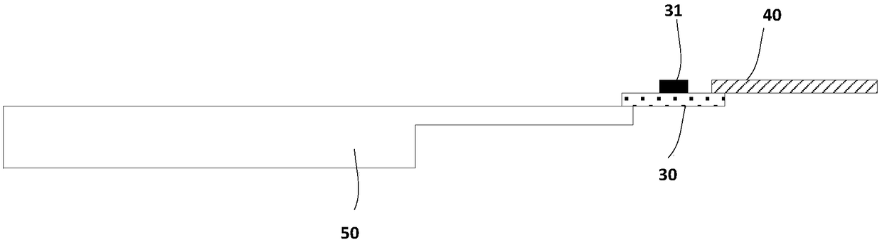
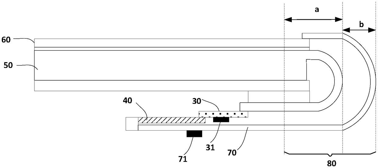
[0048] Please refer to figure 1 , figure 2 with image 3 , figure 1 It is a top view of the binding of the existing display panel with the chip-on-chip film and the main flexible circuit board, figure 2 Side view for existing display panel bonded with COF and main flex circuit board, image 3 It is a side view of an existing touch display device including a display panel and a touch ...


PUM


Abstract

The invention provides a display substrate, a display panel, a touch display device and a manufacturing method thereof. The display substrate comprises a display area and a non-display area. The non-display area is provided with a plurality of first binding pins and a plurality of second binding pins; the first binding pins are bound to a flexible printed circuit board, and part of the first binding pins is connected with a signal line arranged in the display area, so that the signal line can communicate with a driving integrated circuit on the flexible printed circuit board through the firstbinding pins; the second binding pins are bound to the touch panel, and the second binding pins are correspondingly connected with the other part of the first binding pins so that a touch electrode onthe touch panel can communicate with a touch integrated circuit on the flexible printed circuit board through the second binding pins and the first binding pins. The display panel is used so that thebinding step of the touch display device having the display panel in the binding process can be reduced, and an ultra-narrow frame can be realized for the touch display device having the display substrate.

Description


Claims


Application Information

Patent Timeline
Owner BOE TECH GRP CO LTD
Why Eureka
Try Eureka