
Core tube beam column structure for constructional engineering

A construction technology, tube-beam-column technology, applied in the direction of building components, special structures, electrical components, etc., can solve problems such as hindering installation and maintenance, entangled cables, entangled wires or cables, etc.

Inactive Publication Date: 2018-11-06
吴淑霞
View PDF11 Cites 1 Cited by
  • Summary
  • Abstract
  • Description
  • Claims
  • Application Information

AI Technical Summary

Problems solved by technology

[0003] When the core tube beams and columns are used, wires or cables are often placed inside, which is convenient for high-rise buildings. However, due to the lack of reasonable support for the wires or cables inside the core tube beams and columns, the internal cables are often entangled. If installation or maintenance, multiple Wires or cables are entangled, hindering installation and maintenance, and reducing the use effect of core tube beams and columns

Method used


Image

  • Core tube beam column structure for constructional engineering
  • Core tube beam column structure for constructional engineering
  • Core tube beam column structure for constructional engineering

Examples


Embodiment Construction

[0020] The present invention will be further described below in conjunction with the accompanying drawings.

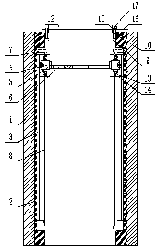
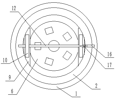
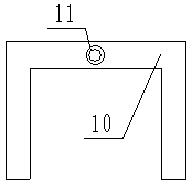
[0021] Such as Figures 1 to 3 As shown, a core tube beam-column structure for a construction project according to the present invention includes a frame 1, a cylinder 2, a pair of slide rails 3, a pair of moving trolleys 4, a pair of support seats 5, a fixed plate 6, two For the fixed frame 7 and the pair of poles 8, the cylinder 2 is placed inside the frame 1, the inner side wall of the cylinder 2 is provided with a pair of first grooves, and the pair of slide rails 3 are arranged in the first grooves Inside, the pair of mobile trolleys 4 are placed on the slide rails 3, the pair of support seats 5 are placed on the pair of mobile trolleys 4, the fixed plate 6 is placed on the pair of support seats 5, and the fixed plate 6 There is a circular through hole at the upper center, several rectangular through holes are opened on the fixed plate 6 and outside the first cir...


PUM


Abstract

The invention relates to the technical field of core tube beam columns, in particular to a core tube beam column structure for constructional engineering. The core tube beam column structure comprisesa frame, a cylinder, a pair of sliding rails, a pair of travelling cars, a pair of support seats, a fixing plate, two pairs of fixing brackets and a pair of support rods, wherein the cylinder is arranged in the frame; a pair of first grooves is formed in a side wall surface in the cylinder; the pair of sliding rails is arranged in the first grooves; the pair of travelling cars is arranged on thesliding rails; the pair of support seats is arranged on the pair of travelling cars; the fixing plate is arranged on the pair of support seats; a circular through hole is formed in the center of the fixing plate; and a plurality of rectangular through holes are formed in the fixing plate and in the outer side of the first circular through hole. According to the core tube beam column structure, theusing effect of the core tube beam column is improved, reasonable portioning arrangement of electric wires or cables is facilitated and the probability that multiple electric wires or cables are entwined with one another is reduced.

Description

technical field [0001] The invention relates to the technical field of core tube beam columns, in particular to a core tube beam column structure for construction engineering. Background technique [0002] The core tube structure belongs to the high-rise building structure. To put it simply, the outer periphery is a frame force system composed of beams and columns, and the middle is a cylinder (such as an elevator shaft). Because the cylinder is in the middle, it is called the core tube, also known as "frame-core tube structure". . [0003] When the core tube beams and columns are used, wires or cables are often placed inside, which is convenient for high-rise buildings. However, due to the lack of reasonable support for the wires or cables inside the core tube beams and columns, the internal cables are often entangled. If installation or maintenance, multiple Wires or cables are entangled, hindering installation and maintenance, and reducing the use effect of core tube be...

Claims


Application Information

Patent Timeline
Patent Type & Authority Applications(China)
IPC IPC(8): H02G3/00E04B1/34
CPCE04B1/34H02G3/00
Inventor 吴淑霞
Owner 吴淑霞
Learn More