
A lower hopper device

A cutting and bucket body technology is applied in the field of cutting and discharging devices to achieve the effects of reducing damage, improving efficiency and reducing potential safety hazards.

Active Publication Date: 2019-12-31
WUHU NEW UNIVERSAL ENVIRONMENTAL SCI TECH
View PDF6 Cites 0 Cited by
  • Summary
  • Abstract
  • Description
  • Claims
  • Application Information

AI Technical Summary

Problems solved by technology

[0003] The purpose of the present invention is to provide a lower hopper device to solve the problems of the rapping device in the prior art that is fixed on the hopper wall and raps and reduces potential safety hazards

Method used


Image

  • A lower hopper device
  • A lower hopper device
  • A lower hopper device

Examples


Embodiment Construction

[0013] In order to make the technical means, creative features, goals and effects achieved by the present invention easy to understand, the present invention will be further described below in conjunction with specific embodiments.

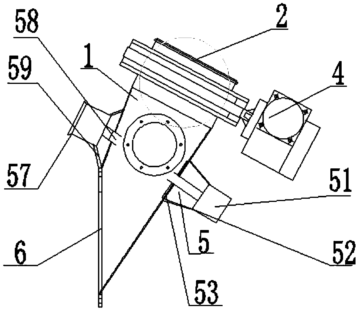
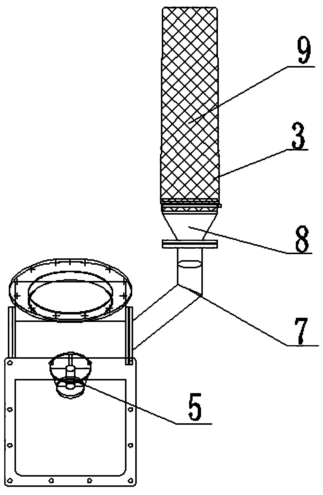
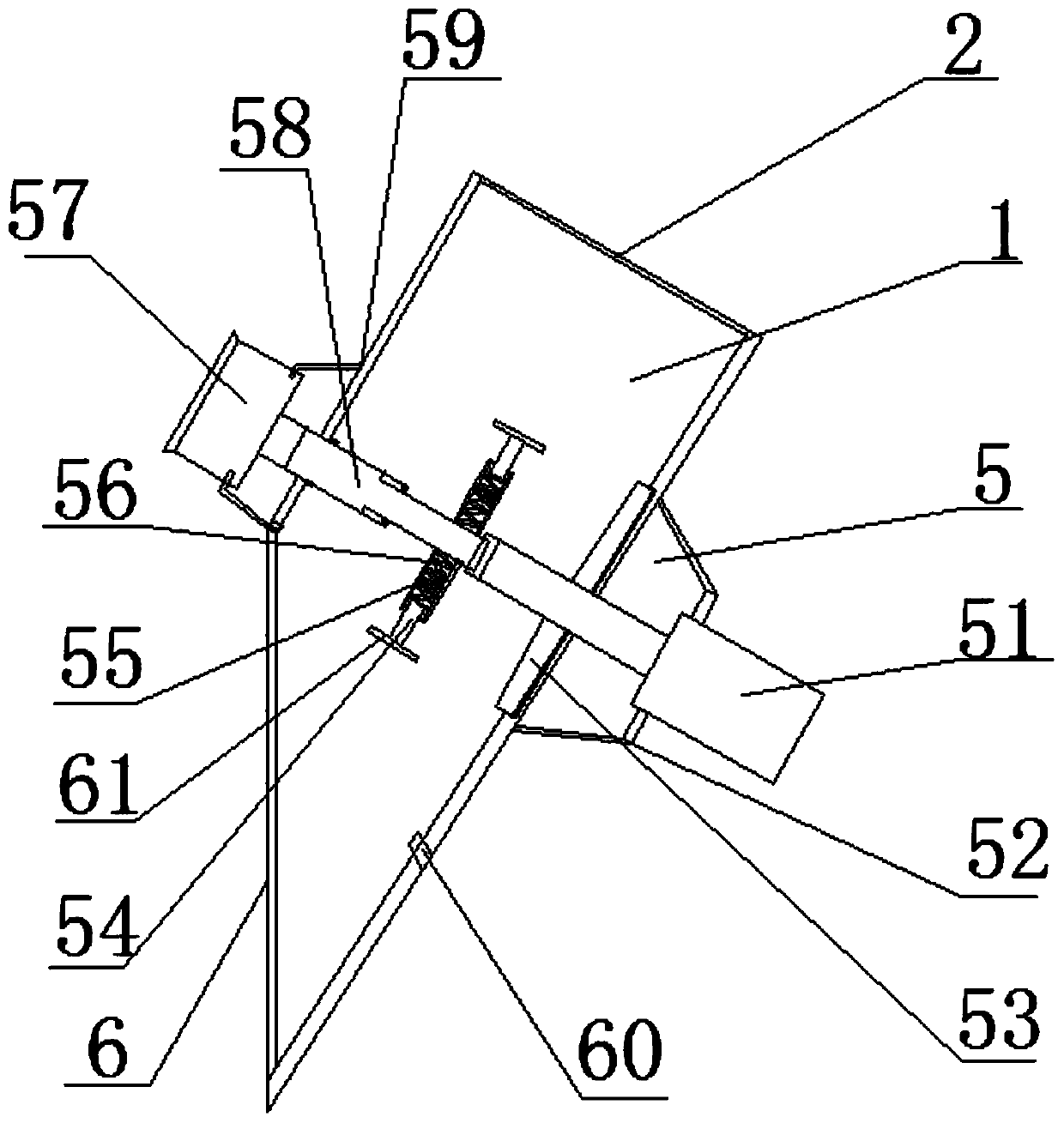
[0014] Such as Figure 1 to Figure 3 As shown, a lower hopper device includes a bucket body 1 and a scraping mechanism 5. The upper end surface of the bucket body 1 is provided with a feed inlet 2, and the lower end surface of the bucket body 1 is provided with a discharge opening 6. The scraping mechanism 5 includes a cylinder 51, a scraping rod 54, a scraping rod mounting seat 56, a motor 57, a retractable rotating shaft 58, and a photoelectric switch 60. An outer wall of the bucket body 1 is equipped with a cylinder mounting seat 52, The other outer wall is equipped with a motor mount 59, the cylinder 51 is installed on the cylinder mount 52, the cylinder telescopic rod of the cylinder 51 penetrates into the bucket body, and the end of the cyli...


PUM


Abstract

The invention discloses a discharging hopper device which comprises a hopper body. An air cylinder mounting base is mounted on one outer wall of the hopper body, and a motor mounting base is mounted on the other outer wall. An air cylinder is mounted on the air cylinder mounting base, and an air cylinder telescopic rod of the air cylinder penetrates into the hopper body. A rotary connector is arranged at the end of the air cylinder telescopic rod, and a plurality of scraping rod mounting bases are evenly arranged on a telescopic rotary shaft. The scraping rod mounting seats stretch out in theradial direction, and tension springs are arranged in the scraping rod mounting bases. Scraping rods are inserted into the scraping rod mounting bases, and scrapers are mounted on the lower side facesof the scraping rods, and the other ends of the scraping rods are in contact with the ends of the tension springs. The other ends of the tension springs are in contact with the scraping rod mountingbases, and a motor is mounted on the motor mounting base. One end of the telescopic rotary shaft penetrates into the hopper body to be fixedly connected with the rotary connector, and the other end ofthe telescopic rotary shaft is connected with the motor output end outside the hopper body. The discharging hopper device is simple in structure and easy to operate, the work positions of the scrapercan be changed, and damage of the scrappers to the hopper body is effectively reduced; and the potential safety hazards of the hopper body are reduced, and production is more stable and efficient.

Description

technical field [0001] The invention relates to a material unloading and discharging device, in particular to a material unloading device for clearing a blockage of a hopper. Background technique: [0002] In the process of conveying powdery, granular, massive or mixed solid materials, due to the high humidity, ash content and high viscosity of the materials, the materials are easy to accumulate at the hopper mouth. When the humidity of the materials is high, most The fluidity of the material is low, and it is easy to harden on the wall of the hopper, resulting in a decrease in the actual flow area, which affects the normal and continuous production; at present, the more commonly used method is to manually hit the hopper with a sledgehammer, or the existing technology in the hopper The rapping devices are fixedly installed on both sides of the wall. The above method can only solve the short-term problem. For a long time, the bucket wall will be damaged or cracked, resulting ...

Claims


Application Information

Patent Timeline
Patent Type & Authority Patents(China)
IPC IPC(8): B65D88/64
CPCB65D88/64
Inventor 张跃东袁野
Owner WUHU NEW UNIVERSAL ENVIRONMENTAL SCI TECH
Learn More