
Boring method for machining hole system of crossing angle box body

A box and hole system technology, applied in the field of corner box processing and manufacturing, can solve the problems of limited machine tool selection and inability to process ordinary boring machines, and achieve the effect of increased machine selection range, good use effect, and low rotation accuracy requirements

Active Publication Date: 2018-11-13
HANGZHOU ADVANCE GEARBOX GRP
View PDF6 Cites 3 Cited by
  • Summary
  • Abstract
  • Description
  • Claims
  • Application Information

AI Technical Summary

Problems solved by technology

[0003] One is that ordinary boring machines cannot process;
[0004] The second is that machine tools with this function are required, and there are limitations in the selection of machine tools

Method used


Image

  • Boring method for machining hole system of crossing angle box body
  • Boring method for machining hole system of crossing angle box body
  • Boring method for machining hole system of crossing angle box body

Examples


Embodiment

[0030] Example: Take the processing of a certain type of corner box as an example, the parameters are: angle 7°±20", the center distance from the big end is 503.48±0.02, and the material is Q235 steel; the implementation steps are as follows:

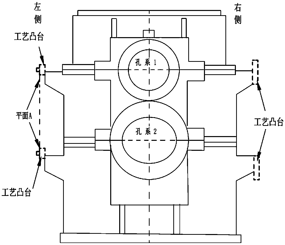
[0031] 1) Communicate with the blank manufacturer to increase the process bosses on the left and right sides, the left side is used for processing pin holes, and the right side is used for parts clamping, such as Figure 10 shown. (This step is implemented in conjunction with the part structure)

[0032] 2) On the left side of the box, process the 4-φ16H7 positioning pin hole and the plane where the pin hole is located according to the hole system requirements of the part drawing and the CAD drawing conversion size, and install 4 pieces of GB119 16X30 cylindrical pins, such as Figure 11 shown.

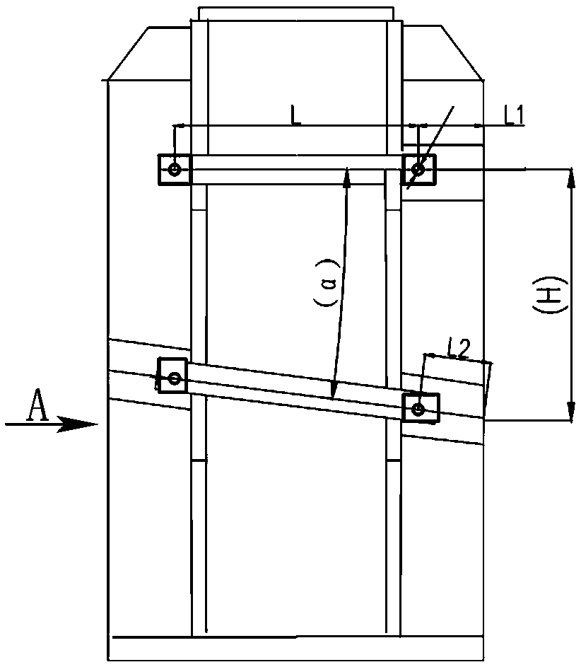
[0033] 3) Put the positioning pin end of the box upwards, press Figure 4 Clamping at the processing position, first align the set of posit...


PUM


Abstract

The invention relates to a boring method for machining a hole system of a crossing angle box body. The boring method comprises the following steps: (a) a machined support surface or bottom surface ofthe angle box body is taken as a positioning reference, after four pin hole positions are drawn on the hole system by computer-aided software through conversion, two groups of positioning pin holes are machined according to coordinates, and then the plane where the pin holes are located is machined; and cylindrical pins are mounted after machining; (b) the crossing angle box body is re-clamped, and the plane where one set of hole system positioning pins and the pin holes in the set are located is corrected; the clamping mode is maintained, after a spindle is moved downwards, the coordinate ofthe vertical hole system center in the radial direction is set as "zero" position, and the axial starting point of the end face of the box body, i.e., the distance from the center of the pin holes isL1 in size, and the vertical hole system is machined; (c) the worktable angle of a machine tool is rotated to alpha, the plane where the other set of hole system positioning pins and the pin holes inthe set are located is corrected, the clamping mode is maintained, the spindle is moved downwards to the radial coordinate "zero" position of the crossing angle hole system, the axial starting point of the end face of the box body, namely, the distance from the center of the pin holes is L2 in size, and the crossing angle hole system is machined.

Description

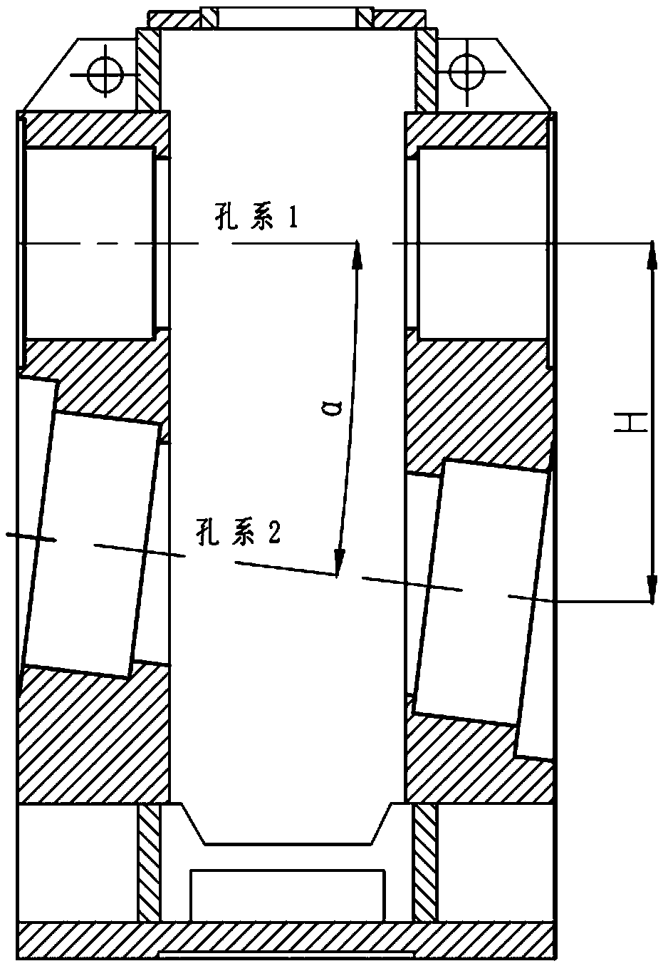
technical field [0001] The invention relates to a boring method for machining the hole system of an angle box, and belongs to the technical field of angle box processing and manufacturing. Background technique [0002] The intersection hole system that needs to be processed is as follows: figure 1 As shown, it requires to ensure the angle α and its center distance H; the existing boring machine processing technology is only limited to the processing of parallel hole systems, and cannot directly process intersecting hole systems. If you need to process intersecting hole systems, you need to choose a high Finishing center. Therefore, the current processing technology of the intersection hole system mainly has the following defects: [0003] One is that ordinary boring machines cannot process; [0004] The second is that machine tools with this function are required, and there are limitations in the selection of machine tools. Contents of the invention [0005] The purpos...

Claims


Application Information

Patent Timeline
Patent Type & Authority Applications(China)
IPC IPC(8): B23B35/00
CPCB23B35/00
Inventor 姚红燕金海明俞宗良
Owner HANGZHOU ADVANCE GEARBOX GRP
Learn More