Friction stir welding equipment for stationary shaft shoulder

A friction stir welding and static shaft shoulder technology, which is applied in welding equipment, non-electric welding equipment, metal processing equipment, etc., can solve the problems of difficult cleaning, easy damage, inconvenient disassembly and replacement, etc., and achieves the effect of increasing practicability

Active Publication Date: 2018-11-13
HUNAN UNIV OF ARTS & SCI
View PDF8 Cites 2 Cited by
  • Summary
  • Abstract
  • Description
  • Claims
  • Application Information

AI Technical Summary

Problems solved by technology

[0004] The invention provides a friction stir welding equipment for static shaft shoulders, which has the advantages of easy removal of waste materials and easy disassembly and replacement of stirring pins, and solves the problem of instability in the welding process of ordinary friction stir welding and serious flash defects, thereby In view of the above problems, a static shoulder friction stir welding was proposed to improve it. Therefore, adding an auxiliary static shoulder can not only reduce the flash, but also inhibit the plasticized material from being extruded from both sides of the rotating stirring needle, preventing defects such as holes. However, when the existing static shoulder friction stir welding is in operation, due to the gap between the static shoulder and the stirring needle, some waste materials will enter the gap during the welding process, which not only makes it difficult to clean up later, but also At the same time, the excessive accumulation of these waste materials in the static shoulder will affect the rotation of the stirring needle, and the stirring needle will be in contact with the outer surface of the workpiece for a long time, resulting in relatively high friction damage and easy damage to the stirring needle. A problem that makes it inconvenient for maintenance personnel to remove and replace it

Method used


Image

  • Friction stir welding equipment for stationary shaft shoulder
  • Friction stir welding equipment for stationary shaft shoulder
  • Friction stir welding equipment for stationary shaft shoulder

Examples


Embodiment Construction

[0025] The technical solutions in the embodiments of the present invention will be clearly and completely described below with reference to the accompanying drawings in the embodiments of the present invention. Obviously, the described embodiments are only a part of the embodiments of the present invention, but not all of the embodiments. Based on the embodiments of the present invention, all other embodiments obtained by those of ordinary skill in the art without creative efforts shall fall within the protection scope of the present invention.

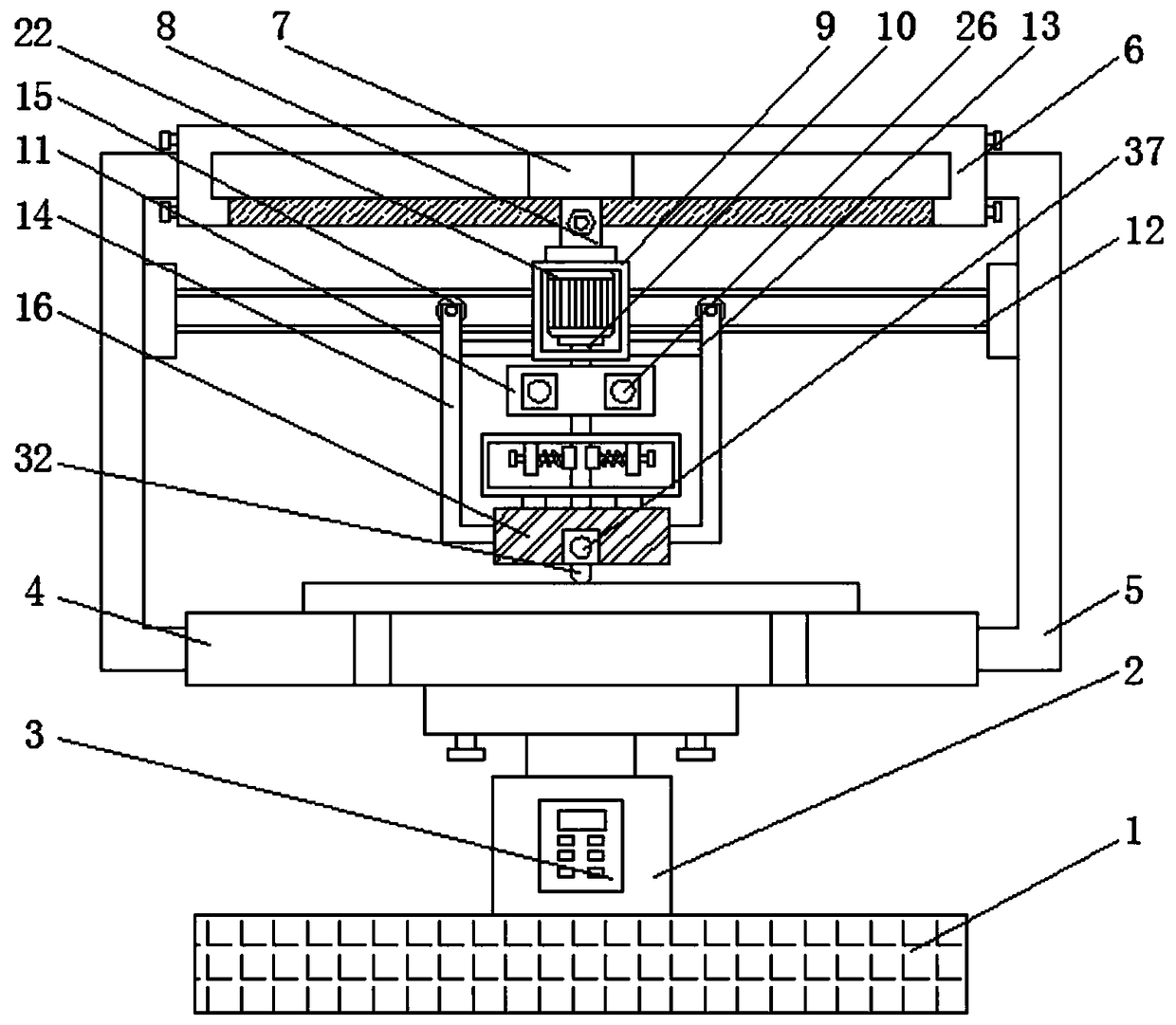
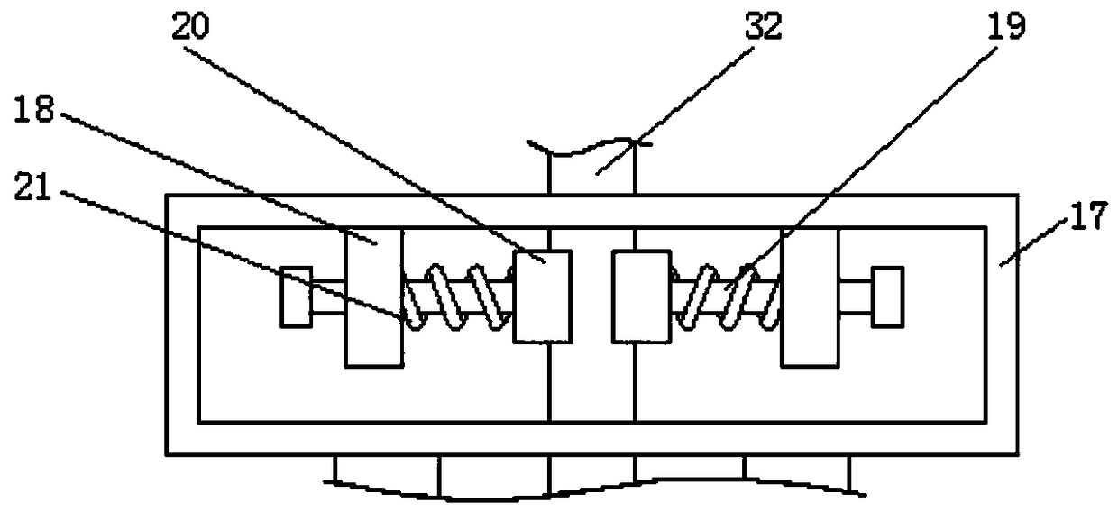
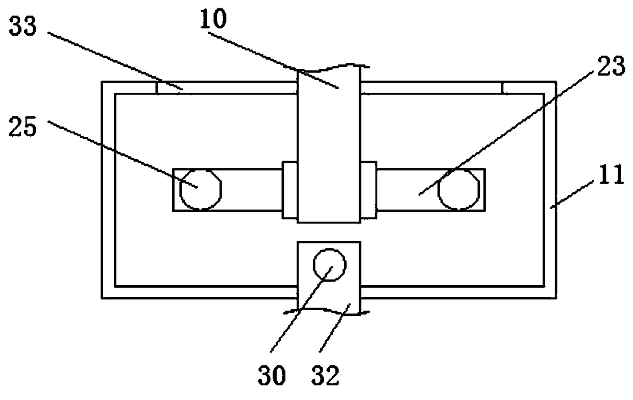
[0026] see Figure 1-6, a friction stir welding equipment for stationary shaft shoulders, including a base 1 and a rectangular box 11, the distance between the bottom of the rectangular box 11 and the top of the installation box 17 can be installed according to the actual situation, so as to facilitate the connection between the rectangular box 11 and the side block 23 The box 29 between the pull rods 25 is fixedly installed on the to...


PUM


Abstract

The invention relates to the technical field of friction stir welding, and discloses friction stir welding equipment for a stationary shaft shoulder. The friction stir welding equipment comprises a base and a rectangular box; and a jacking block is fixedly mounted in the middle of the top end of the base, a transverse plate is fixedly mounted on the top of the jacking block, and a control unit isfixedly mounted on the obverse side of the jacking block. According to the friction stir welding equipment for the stationary shaft shoulder, by forming a square opening and a collecting box, when thebottom of a stirring needle body conducts friction welding on a workpiece, waste materials generated at the time penetrate through a gap between a stationary shaft shoulder body and the stirring needle body to enter the collecting box, the cross sectional area of the side face of the square opening is equal to the cross sectional area of the side face of the collecting box, thus the collecting box can be taken out of the stationary shaft shoulder body, the problem that the waste materials in the stationary shaft shoulder body are difficult to dispose is prevented, meanwhile, the situation that rotating of the stirring needle body is affected by the excessive waste materials in the stationary shaft shoulder body is also avoided, and the practicality of the friction stir welding equipment is improved.

Description

technical field [0001] The invention relates to the technical field of friction stir welding, in particular to a friction stir welding equipment for a stationary shaft shoulder. Background technique [0002] Friction stir welding is a solid phase joining technology invented in 1991, especially suitable for welding low melting point alloys such as aluminum. Friction stir welding uses the friction heat generated by the shaft shoulder and the friction between the stirring needle and the workpiece to make the material near the welded joint reach a plastic state, and the fluidity of the material increases. Under the stirring action of the stirring needle, it is moved to the back of the stirring head and cooled to form a welded joint. During the welding process, the material is not melted, and the maximum temperature is about 80% of the melting point of the material to be welded. [0003] The usual friction stir welding is unstable in the welding process, and the flash defects ar...

Claims


Application Information

Patent Timeline
Patent Type & Authority Applications(China)
IPC IPC(8): B23K20/12B23K20/26
CPCB23K20/1245B23K20/125
Inventor 李志刚李叶林杨小高罗佑新
Owner HUNAN UNIV OF ARTS & SCI
Why Eureka
Try Eureka