
Fixing device for glass grinding of GPS
A fixing device and glass technology, which is applied in grinding/polishing safety devices, lighting devices, lighting devices, etc., can solve the problems of simple structure of glass fixing devices, human injury, affecting grinding work, etc., to avoid the impact of precision and protect Environmental and practical effects
- Summary
- Abstract
- Description
- Claims
- Application Information
AI Technical Summary
Problems solved by technology
Method used
Image

Examples
Embodiment Construction
[0013] The present invention will be further described below in conjunction with accompanying drawing.
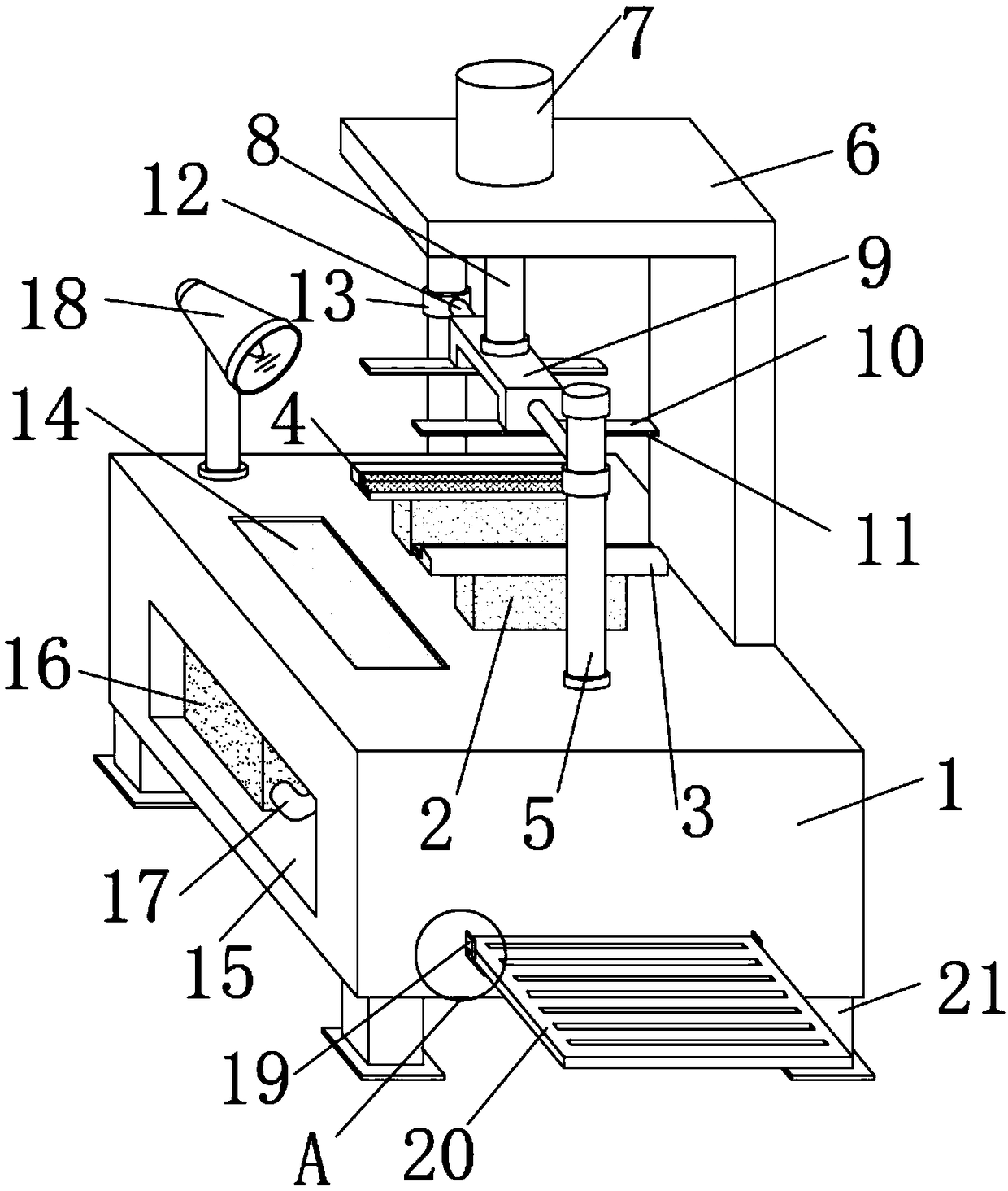
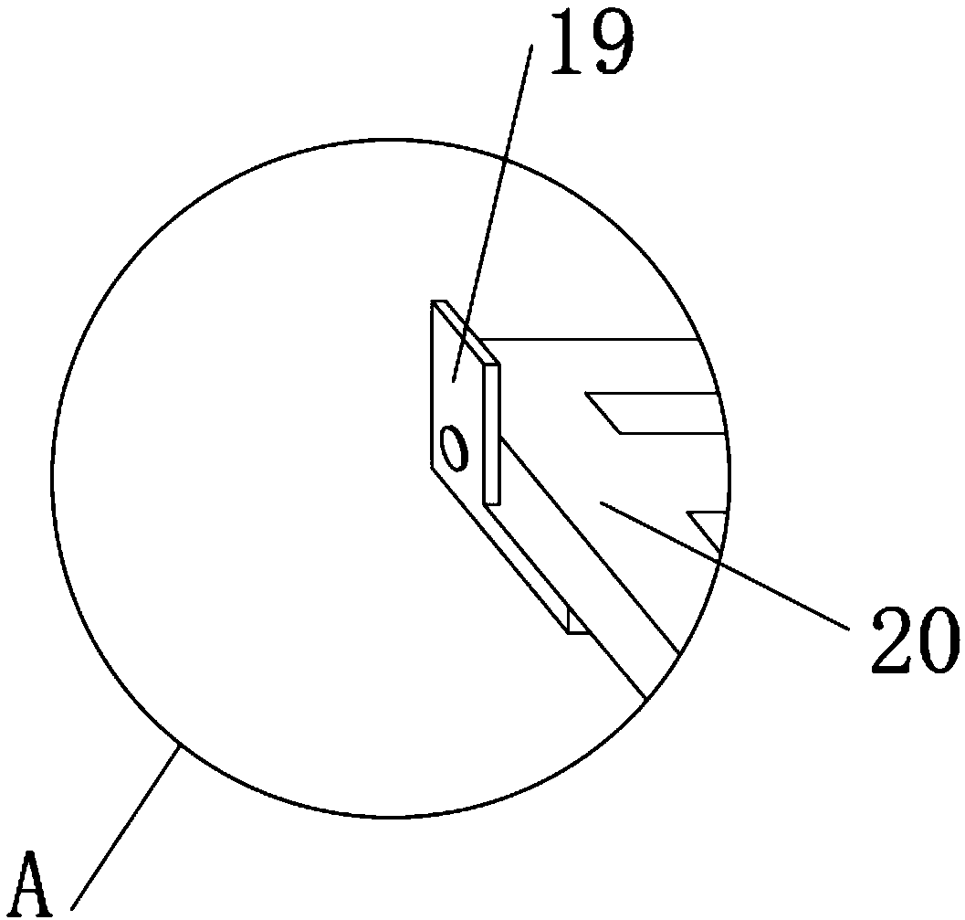
[0014] Such as Figure 1-2 As shown, a GPS glass polishing fixing device includes a device table 1, two lower supports 2 are fixedly installed in the middle of the upper end surface of the device table 1, and a lower supporting plate 3 is fixedly installed on the upper end of the lower support 2, and the lower support The upper end of the plate 3 is provided with a bracket and the lower rubber pad 4 is arranged in the bracket, and the outer side of the lower support 2 is provided with a slide bar 5, the lower end of the slide bar 5 is fixedly connected with the device table 1, and the upper end surface of the device table 1 is fixedly installed There is an upper support 6 with an L-shaped structure, and a cylinder 7 is fixedly installed in the middle of the upper end surface of the upper support 6. The output end of the cylinder 7 is fixedly connected with a telescopic rod ...
PUM
 Abstract
Description
Claims
Application Information