An energy-saving and environment-friendly lime kiln for flue gas reuse
An energy-saving and environment-friendly lime kiln technology, which is applied to furnaces, furnace components, lighting and heating equipment, etc., can solve the problems of waste and waste heat of high-temperature flue gas not being used, and achieve the effect of increasing furnace temperature and obvious energy-saving effect
- Summary
- Abstract
- Description
- Claims
- Application Information
AI Technical Summary
Problems solved by technology
Method used
Image

Examples
specific Embodiment approach 1
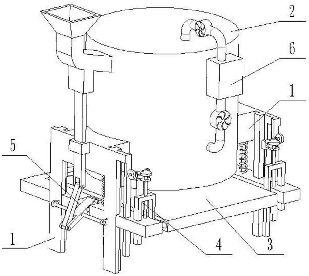
[0025] Combine below Figure 1-8 Describe this embodiment, an energy-saving and environment-friendly lime kiln for flue gas reuse, including a support 1, a kiln 2, an ash receiving seat 3, an ash unloading control part 4, a feed control part 5 and a flue gas circulation control processing part 6, There are two supports 1, the kiln 2 is connected between the two supports 1, the ash receiving seat 3 is slidably connected on the two supports 1, the ash receiving seat 3 is located directly below the kiln 2, and the two unloading seats The ash control parts 4 are symmetrically arranged at both ends of the ash receiving seat 3, and there are two ash discharge control parts 4, and the two ash discharge control parts 4 are respectively connected with the two brackets 1, and the feed control part 5 is set on one of the brackets 1, the left end of the ash receiving seat 3 is connected to the feeding control part 5, and the upper end of the feeding control part 5 is connected to the kiln...
specific Embodiment approach 2
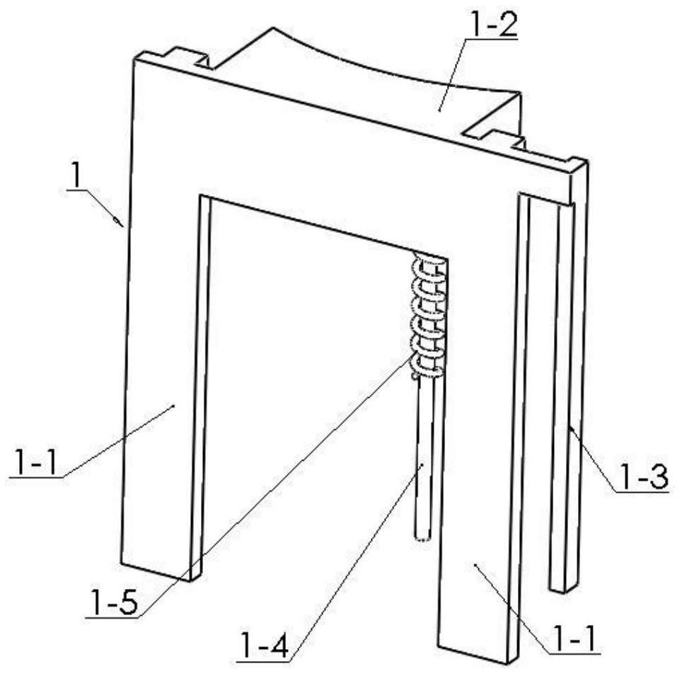
[0027] Combine below Figure 1-8 To illustrate this embodiment, the bracket 1 includes a T-shaped riser 1-1, a connecting seat 1-2, a rack 1-3, a spring sleeve rod 1-4 and a spring 1-5, and the connecting seat 1-2 is fixedly connected On the upper ends of the two T-shaped vertical plates 1-1, the rack 1-3 is fixedly connected to the T-shaped vertical plate 1-1 at the front end, and the lower end of the connecting seat 1-2 is fixedly connected with a spring sleeve rod 1-4, and the spring Spring 1-5 is sleeved on sleeve bar 1-4.
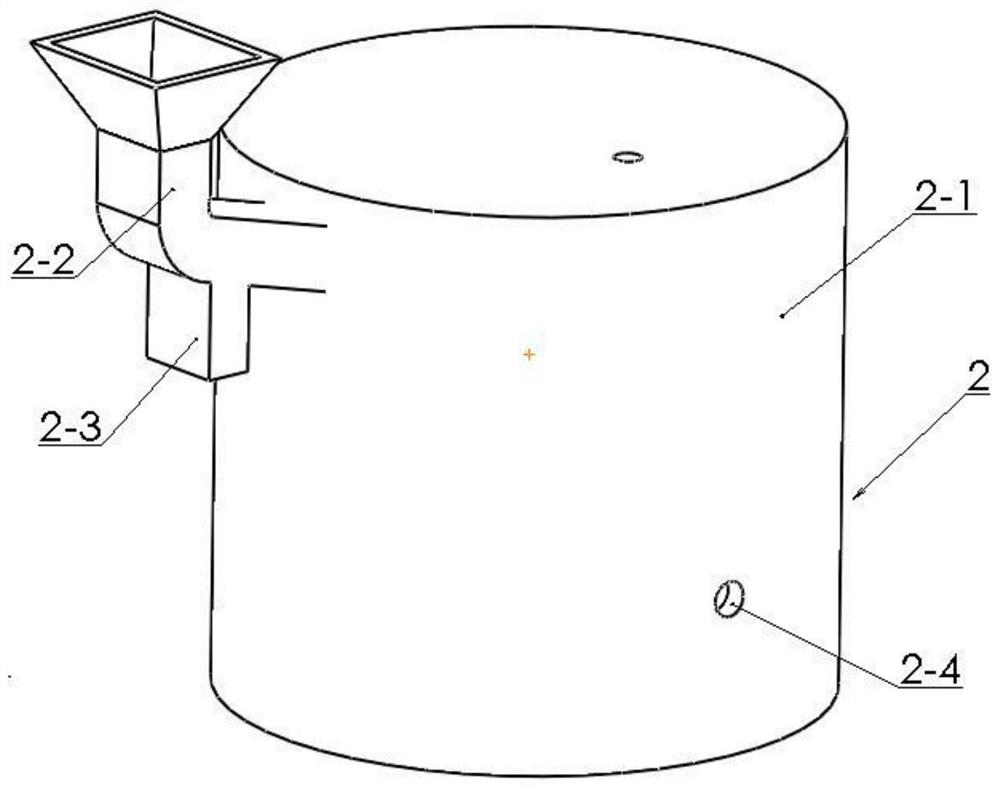
[0028] The kiln 2 includes a furnace body 2-1, a feed pipe 2-2, a baffle slide 2-3, an air inlet 2-4 and an ash filter plate 2-5 with a plurality of sieve holes. The lower end of 2-1 is hollowed out, the furnace body 2-1 is fixedly connected between the two connection seats 1-2, the upper end of the furnace body 2-1 is connected and communicated with the feed pipe 2-2, and the lower end of the feed pipe 2-2 Connect and communicate with the baffle sli...
specific Embodiment approach 3
[0032] Combine below Figure 1-8 To illustrate this embodiment, the feed control member 5 includes a rod frame 5-1, a shaft rod 5-2, a rotating rod 5-3, a cylindrical rod chute 5-4, a cylindrical rod 5-5, and a connecting rod 5- 6. The reciprocating baffle plate 5-7 and the fixed sliding sleeve 5-8, the shaft rod 5-2 are fixedly connected between the two rod frames 5-1, and the two rod frames 5-1 are fixedly connected to the two T-shaped On the vertical plate 1-1, the middle end of the rotating rod 5-3 is rotatably connected to the shaft rod 5-2, and one end of the rotating rod 5-3 is provided with a cylindrical rod chute 5-4, and the cylindrical rod 5-5 is slidably connected to the In the cylindrical rod chute 5-4, the two ends of the cylindrical rod 5-5 are respectively fixedly connected to the two ends of the cylindrical rod placement groove 3-3, and the other end of the rotating rod 5-3 is connected with the connecting rod 5-3 through the hinge shaft. 6. The upper end of ...
PUM
 Abstract
Description
Claims
Application Information
 - R&D
- Intellectual Property
- Life Sciences
- Materials
- Tech Scout
- Unparalleled Data Quality
- Higher Quality Content
- 60% Fewer Hallucinations
Browse by: Latest US Patents, China's latest patents, Technical Efficacy Thesaurus, Application Domain, Technology Topic, Popular Technical Reports.
© 2025 PatSnap. All rights reserved.Legal|Privacy policy|Modern Slavery Act Transparency Statement|Sitemap|About US| Contact US: help@patsnap.com