Dehydration structure of washing machine

A technology of dehydration structure and washing machine, applied in the field of washing machine, to achieve the effect of clear design concept, increased volume, and improved washing capacity

Active Publication Date: 2018-11-13
QINGDAO HAIER WASHING MASCH CO LTD +2
View PDF4 Cites 12 Cited by
  • Summary
  • Abstract
  • Description
  • Claims
  • Application Information

AI Technical Summary

Problems solved by technology

In the dehydration structure of the washing machine according to the present invention, the dehydration port closed by the dehydration valve is provided at the large mouth end of the inner cylinder, so that when the inner cylinder rotates at a high speed, the water in the inner cylinder will converge and flow to the large mouth end under the action of centrifugal force, and the dehydration valve core will be closed. Centrifugal force drives the opening to solve the problem of how to drain the water from the clothes in the inner drum, and then realizes the sealing of the rotatable inner drum mouth, the water in the inner drum does not leak out during the normal working process of the washing machine, and the clothes are separated from the water when the washing machine is dehydrating The purpose of draining through the dehydration waterway; at the same time, the inner and outer cylinders of the drum washing machine are combined into one, so as to realize the purpose of expanding the washing capacity of the washing machine

Method used


Image

  • Dehydration structure of washing machine
  • Dehydration structure of washing machine
  • Dehydration structure of washing machine

Examples


Embodiment 1

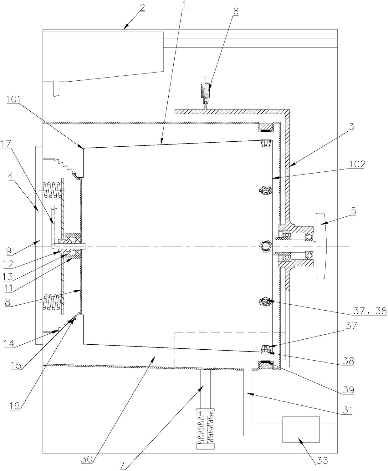
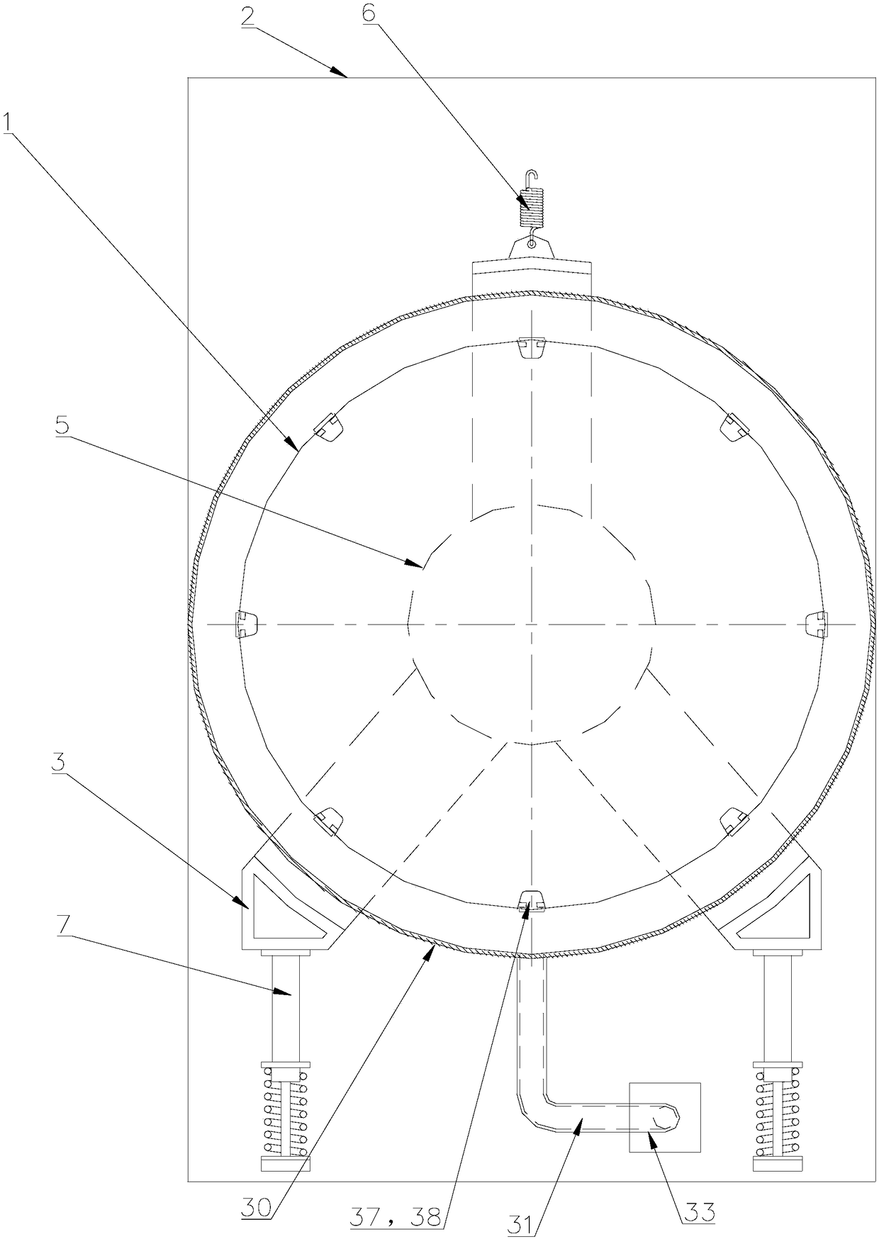
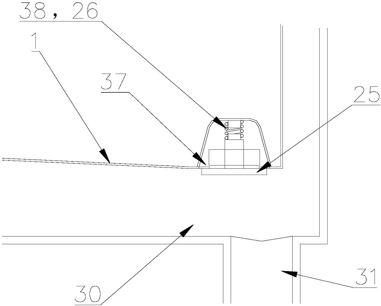
[0043] Such as Figure 1 to Figure 4 As shown, a dehydration structure of a washing machine is introduced in this embodiment. An inner cylinder 1 is installed in the washing machine housing 2, and at least one dehydration port 37 is provided on the side wall of the inner cylinder, and dehydration valves 38 are respectively provided at the dehydration ports 37. , the spool 25 of the dehydration valve 38 is connected with the inner tube 1 through the limit spring 26, and the spool 25 is closed by the action of the limit spring 26 to close the dehydration port 37; when the inner tube 1 rotates for dehydration, the rotating centrifugal force overcomes the limit spring 26 The elastic force of the push valve core 25 moves and opens the dehydration valve 38 to drain water.

[0044] In this embodiment, the inner cylinder 1 is set as a tapered cylinder with a small diameter at one end and a larger diameter at the other end, and the dehydration port 37 is arranged at the side wall of th...

Embodiment 2

[0054] In this embodiment, in order to realize the sealing at the mouth 101 of the inner cylinder when the washing machine is working, the following settings are made:

[0055] Such as figure 1 As shown, a washing machine, a door cover 4 is installed on the washing machine shell 2, and the door cover 4 is relatively rotatably connected with the inner cylinder cover 8 through the elastic mechanism, so that the elastic mechanism provides the inner cylinder cover 8 with the door cover 4 closed. The locking elastic force makes the inner cylinder cover 8 and the inner cylinder mouth 101 in sealing contact, and makes the inner cylinder cover 8 rotate together with the inner cylinder 1, so that the inner cylinder cover 8 is fastened to the inner cylinder mouth 101 after the door cover 4 is closed. The purpose of inner cylinder 1 sealing.

[0056] Through the above settings, the inner cylinder cover at the mouth of the inner cylinder is sealed by elastic force. During the washing pro...

Embodiment 3

[0071] The difference between this embodiment and the above-mentioned embodiment 1 is that a washing machine can use the dehydration structure described in the above-mentioned embodiment 1 to drain water, so as to discharge the water contained in the inner cylinder of the washing machine to achieve the purpose of draining the water from the washing machine.


PUM


Abstract

The invention relates to a dehydration structure of a washing machine. An inner tub is installed inside a washing machine shell. At least one dehydration opening is formed in the side wall of the inner tub, a dehydration valve is arranged at the dehydration opening, a valve element of the dehydration valve is connected with the inner tub through a limiting spring, and the valve element closes thedehydration valve under the effect of the limiting spring; when the inner tub dehydrated and rotates, rotating centrifugal force overcomes elasticity of the limiting spring to push a valve element tomove and turn on the dehydration valve to drain water. In this way, when the inner tub rotates normally, water contained in the inner tub cannot flow out from the dehydration opening, the effects thatthe inner tub is sealed in the inner tub washing process, during dehydration, the dehydration valve opens the inner tub under the effect of centrifugal force, and water is drained from clothes and drained outside normally are achieved, and the purpose of normal dehydration of the washing machine with the dual effects of inner tub rotation and water containing is achieved; meanwhile, the inner tubdoes not need to be sleeved with an outer tub, the volume of the inner tub is increased, and the washing capacity of the washing machine is improved.

Description

technical field [0001] The invention belongs to the technical field of washing machines, and in particular relates to a washing machine with only a rotatable and water-holding inner cylinder, in particular to a dehydration structure of the washing machine. Background technique [0002] In the prior art, a drum washing machine generally includes an inner cylinder and an outer cylinder that fit each other, the outer cylinder is sealed to hold water, the inner cylinder is used to hold clothes, and the inner cylinder is rotated to beat and wash the clothes; at the same time, the inner cylinder is Set the dehydration hole so that the water in the outer cylinder flows into the inner cylinder through the dehydration hole to soak the clothes in the inner cylinder, the water in the inner cylinder flows out to the outer cylinder through the dehydration hole, and the moisture on the clothes in the inner cylinder is dehydrated when the inner cylinder rotates at high speed The hole is di...

Claims


Application Information

Patent Timeline
IPC IPC(8): D06F37/04D06F39/08
CPCD06F37/04D06F39/083Y02B40/00
Inventor 吕佩师吴迪李以民劳春峰许升吕艳芬郝兴慧
Owner QINGDAO HAIER WASHING MASCH CO LTD
Why Eureka
Try Eureka