Cast-in-situ bridge Bailey supporting bracket system

A support system and cast-in-place bridge shell technology, which is applied to bridges, bridge construction, erection/assembly of bridges, etc., can solve the problems of inconvenient life for citizens and heavy traffic flow, and achieve fast construction speed, safety assurance, and simple process operation Effect

Inactive Publication Date: 2018-11-13
王远
View PDF0 Cites 0 Cited by
  • Summary
  • Abstract
  • Description
  • Claims
  • Application Information

AI Technical Summary

Problems solved by technology

[0002] This system is deepened based on the conventional Bailey beam erection and dismantling method, which can quickly solve the limitations of the conventional Bailey bea

Method used


Image

  • Cast-in-situ bridge Bailey supporting bracket system
  • Cast-in-situ bridge Bailey supporting bracket system
  • Cast-in-situ bridge Bailey supporting bracket system

Examples


Example Embodiment

[0016] The present invention will be further described in detail below in conjunction with the drawings and specific embodiments:

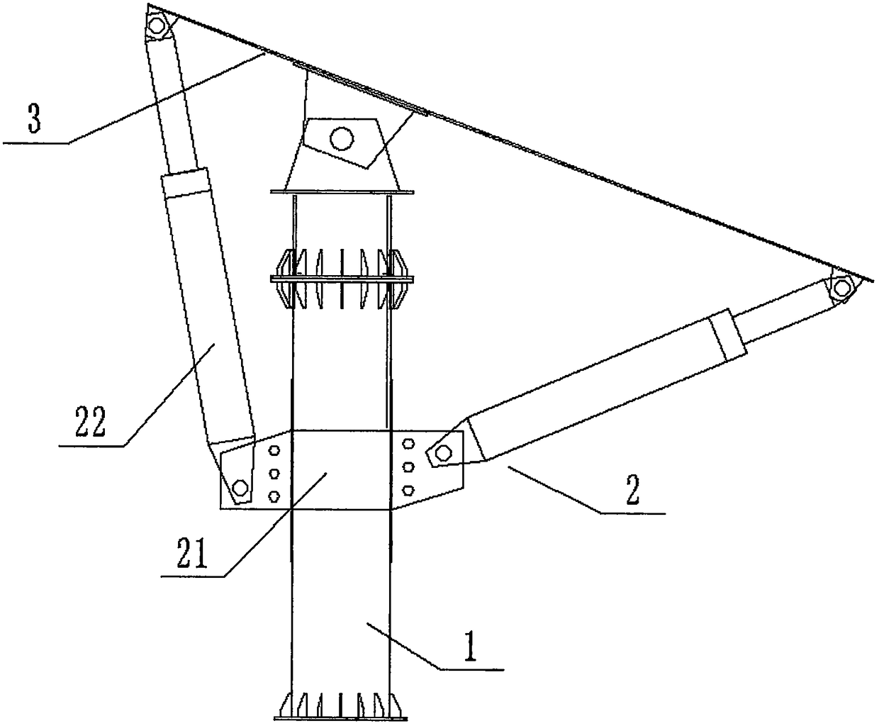
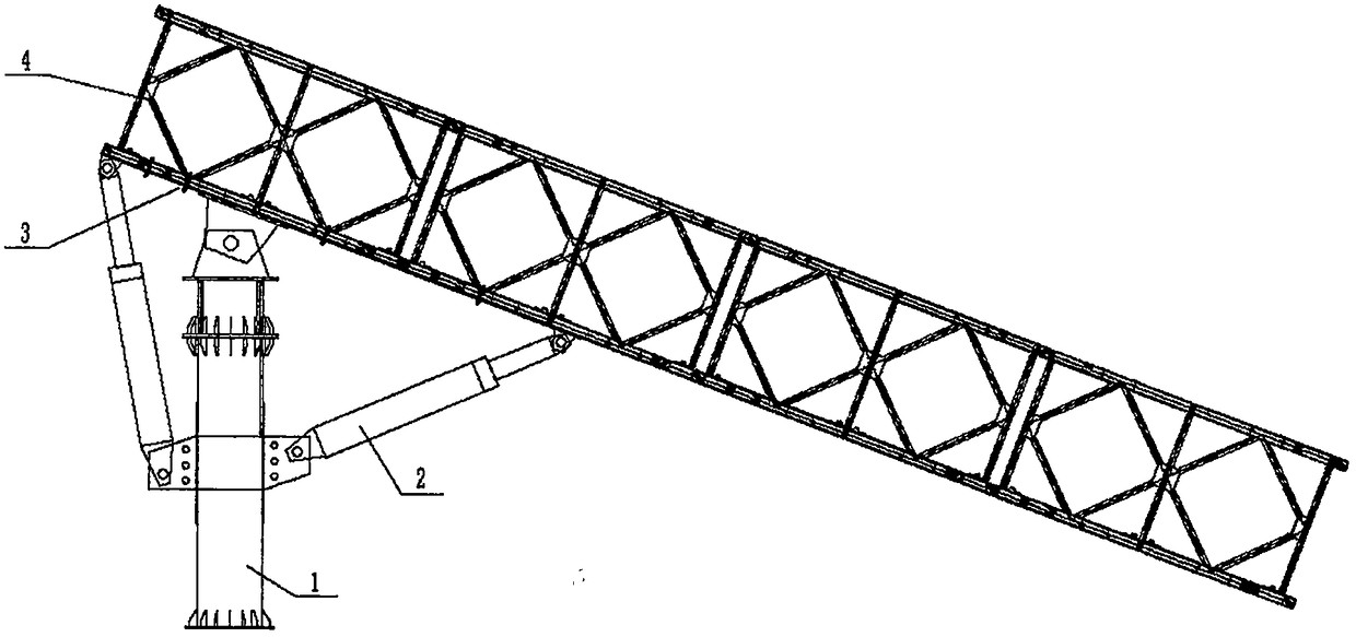
[0017] Such as Figure 1-5 As shown, a cast-in-place bridge Bailey support system includes two steel pipe piles (1) longitudinally forming a support bracket, and the two steel pipe piles (1) are respectively provided with a hydraulic system (2): and The hydraulic system (2) is connected to the steel pipe pile (1) through a rotating base (21); the rotating base (21) can be rotated on the installed horizontal plane: the rotating base (21) Two hydraulic rods (22) are respectively movably connected at both ends of the two hydraulic rods; the free ends of the two hydraulic rods (22) are respectively connected to the two ends of the bearing plate (3); and the middle end of the bearing plate (3) is movable Installed at the top of the steel pipe pile (1); the assembled beret beam (4) is suspended on the bearing plate (3) to avoid the beret beam (4) from bei...


PUM


Abstract

The invention discloses a cast-in-situ bridge Bailey supporting bracket system. The cast-in-situ bridge Bailey supporting bracket system comprises two steel pipe piles forming a supporting bracket ina longitudinally upwards mode. Hydraulic systems are correspondingly arranged at the two steel pipe piles. The hydraulic systems are connected with the steel pipe piles by a rotating base. The rotating base can rotate on installation plane. Two ends of the rotating base are correspondingly rotatably connected with two hydraulic rods. The free ends of the two hydraulic rods are correspondingly connected with two ends of a bearing plate. The middle end of the bearing plate is rotatably mounted at the top ends of the steel pipe piles. A well assembled Bailey beam is hoisted onto the bearing plateand is fixed by U-bolts. Compares with an existing traditional Bailey beam erecting method, the method has the characteristics of being high in security and economical efficiency, avoids inconvenience of blocking traffic flow during urban overpass bridge construction, solves the problem of being unable of being on a crane, and security is guaranteed. The technology operation is simple and construction speed is high.

Description

technical field [0001] The invention belongs to the field of building support systems, and in particular relates to a Bailey support system for cast-in-situ bridges. Background technique [0002] This system is deepened based on the conventional Bailey beam erection and dismantling method, which can quickly solve the limitations of conventional Bailey beams, especially in cities where there is a large traffic flow, and the erection of brackets must cut off traffic, which brings a lot of inconvenience to citizens' lives. Drawing lessons from the construction method of planar rotation and vertical rotation in bridge construction, and further designing and optimizing, the safety and economical effects in actual construction are very obvious. To sum up, so I designed a cast-in-place bridge Bailey support system. Contents of the invention [0003] In order to solve the above existing problems, the present invention provides a cast-in-place bridge bailey support system. [000...

Claims


Application Information

Patent Timeline
IPC IPC(8): E01D21/00
CPCE01D21/00
Inventor 王远
Owner 王远
Why Eureka
Try Eureka